Lithography Stage Rigidity Maps: Mapping Structural Compliance to Overlay Error
A lithography stage is not one stiffness value. Its structural compliance changes with position, direction, payload, and frequency, and those variations print themselves directly into overlay and field-stitching results. This guide explains what a rigidity map is, how compliance becomes overlay error, how to measure the map with force excitation and interferometry, and how to use it in error budgets, servo tuning, and exposure sequencing.
Published
DIRECT ANSWER
What should a buyer prioritize?
A rigidity map is a measured description of how a lithography stage's structure deflects under load as a function of position, direction, and frequency. Every machine tool and lithography stage is a spring network: the base, guides, drive couplings, air film, chuck, and column each contribute compliance, and the resulting stiffness is not constant across travel. When the stage carries its payload to the left edge of the write field the load path through the structure is a different spring set than at the right edge, so the same drive force produces slightly different structural deflection—and the exposure head writes at a position that differs from what the feedback sensor reports.
The overlay consequence is systematic, not random: compliance that varies across travel produces position-dependent scale error and field distortion, compliance that varies with direction produces hysteresis-like reversal gaps even with frictionless air bearings, and compliance that varies with frequency produces velocity- and acceleration-dependent errors during write-on-the-fly exposure. Mapping the rigidity—applying calibrated forces at defined stage positions and directions while measuring deflection with interferometers or the encoder chain itself—turns these errors from unexplained residuals into a compensated, budgeted quantity, and often reveals that the stiffest structure is not the one with the best overlay.
ENGINEERING CONTEXT
The decision starts with the real constraint.
Most stage specifications state a single stiffness figure, usually for the guide system, at an unstated position and direction. The actual machine is more complicated: the compliance that matters for overlay is the compliance between the exposure optical axis and the substrate surface, summed through every load-bearing element between them, and it changes as the stage moves, as the payload changes, and as the exposure head or column loading shifts. Teams routinely observe overlay or stitching residuals that no amount of encoder calibration removes—the encoder genuinely reads the scale position correctly, but the scale and the substrate surface move differently under process loads such as vacuum chucking, focus on-axis forces, or write-head positioning. The result is an error signature that looks like scale error in one direction, like squareness error in another, and like a mystery in the corner of the field. Because the structural error migrates between signatures when anything in the load path changes—a heavier substrate, a new autofocus mechanism, a modified cable chain—diagnosis by pattern-matching against textbook error types often fails, and the machine gets blamed for a mechanical property that was never measured in the first place.
Specify stiffness as displacement of the substrate surface relative to the optical axis per unit force—not guide stiffness, not base mass, but the complete structural loop that separates the writing point from the workpiece.
02
Position and direction dependence measured
The map must cover the stage travel in both horizontal directions and at least the dominant vertical load cases, because stiffness varying across travel is precisely what converts structure into scale error and field distortion.
03
Separation of static and dynamic behavior
Quasi-static force-deflection data and frequency-dependent compliance answer different questions; a map built only from slow push tests will miss the resonance-dominated errors that appear at write velocity.
04
A defined compensation and re-verification path
Every mapped compliance term should have a destination: a compensation table, a servo bandwidth decision, a mechanical redesign, or an explicit line in the overlay error budget with its own uncertainty.
BUYER MATRIX
Compare evidence, not feature labels.
Give every shortlisted supplier the same process definition and request configuration-specific proof.
Three ways to characterize stage rigidity, and what each one buys the overlay engineer
Aspect
Single stiffness figure (datasheet)
Static rigidity map (position-resolved)
Dynamic compliance map (frequency-resolved)
What is measured
One force-deflection slope, usually for the guide or drive, at one nominal position
Deflection of the exposure-to-substrate loop at many positions and directions across travel
Deflection versus excitation frequency, capturing resonances and anti-resonances of the structure
Overlay errors it explains
Little by itself; useful only as a coarse screening figure between machine options
Position-dependent scale error, field distortion, substrate-chuck settling, direction-dependent reversal gaps
Velocity- and acceleration-dependent errors during scanning or write-on-the-fly exposure, servo-structure interaction, settling time after moves
Typical measurement effort
None beyond the vendor statement
Calibrated force application plus interferometer or encoder-chain readings at a grid of stage positions
Modal impact testing, shaker excitation, or drive-current-based identification, plus FFT analysis at several positions
Main limitation
Says nothing about where in travel the stage is compliant, or in which direction
Misses resonance effects; slow loading hides what exposure velocity will see
Interpretation requires servo knowledge; the map changes if the payload or structure is modified
What a stage rigidity map actually measures
The quantity that matters in lithography is the displacement of the exposure point relative to the substrate surface, per unit of disturbing force, evaluated everywhere the process operates. That is a structural loop statement, not a component specification. The loop includes the base and its isolation, the guide or air film, the drive coupling and motor mount, the stage casting, the chuck, and—on the other end of the loop—the column and exposure optics carrying structure. A rigidity map reduces this loop to numbers: at stage position (x, y), pushed in direction d with force F, the loop deflects by δ. Repeating that experiment over a grid of positions and the relevant load directions produces the map.
The reason a single stiffness figure fails is that structural compliance is rarely constant across travel. A cantilevered stage table stiffens as it retracts onto full support and softens at extended positions; air film stiffness changes with the pressure distribution under the pad as the center of gravity shifts; cable chains and flexible conduits add position-dependent spring forces of their own. Two stages with identical datasheet stiffness can therefore print very different grids, and the difference only becomes visible once the map is measured or—less desirably—once it appears as unexplained overlay residuals.
How structural compliance becomes overlay error
Compliance converts force into displacement, and a lithography stage is full of forces the error budget may not have listed: vacuum chucking pulls the substrate against the chuck and reacts on the stage table; autofocus probes the surface and pushes back; write-head focus servos apply vertical forces; cable chains drag; acceleration of the stage mass loads its own mounts. Each force passes through the structural loop, and each produces a displacement that the encoder cannot see if the scale sits on a different part of the loop than the substrate surface. The measured position stays clean while the printed geometry carries the structure's contribution.
Three signatures dominate in practice. Position-dependent compliance across travel appears as scale-like error and field distortion, because the effective measurement origin shifts with stage location. Direction-dependent compliance appears as a reversal error, even on frictionless air bearings, because loading the structure in the +X direction leaves it in a different elastic state than loading it in −X. Frequency-dependent compliance appears as velocity-related error during continuous exposure and as settling behavior after moves. A useful discipline is to assign every structural term a home in the budget with the same seriousness as thermal or Abbe terms, rather than absorbing them into a repeatability figure where they cannot be compensated.
Measuring the map: force excitation, interferometry, and the encoder chain
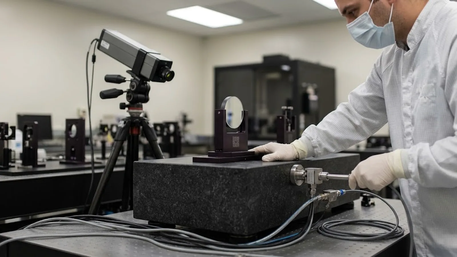
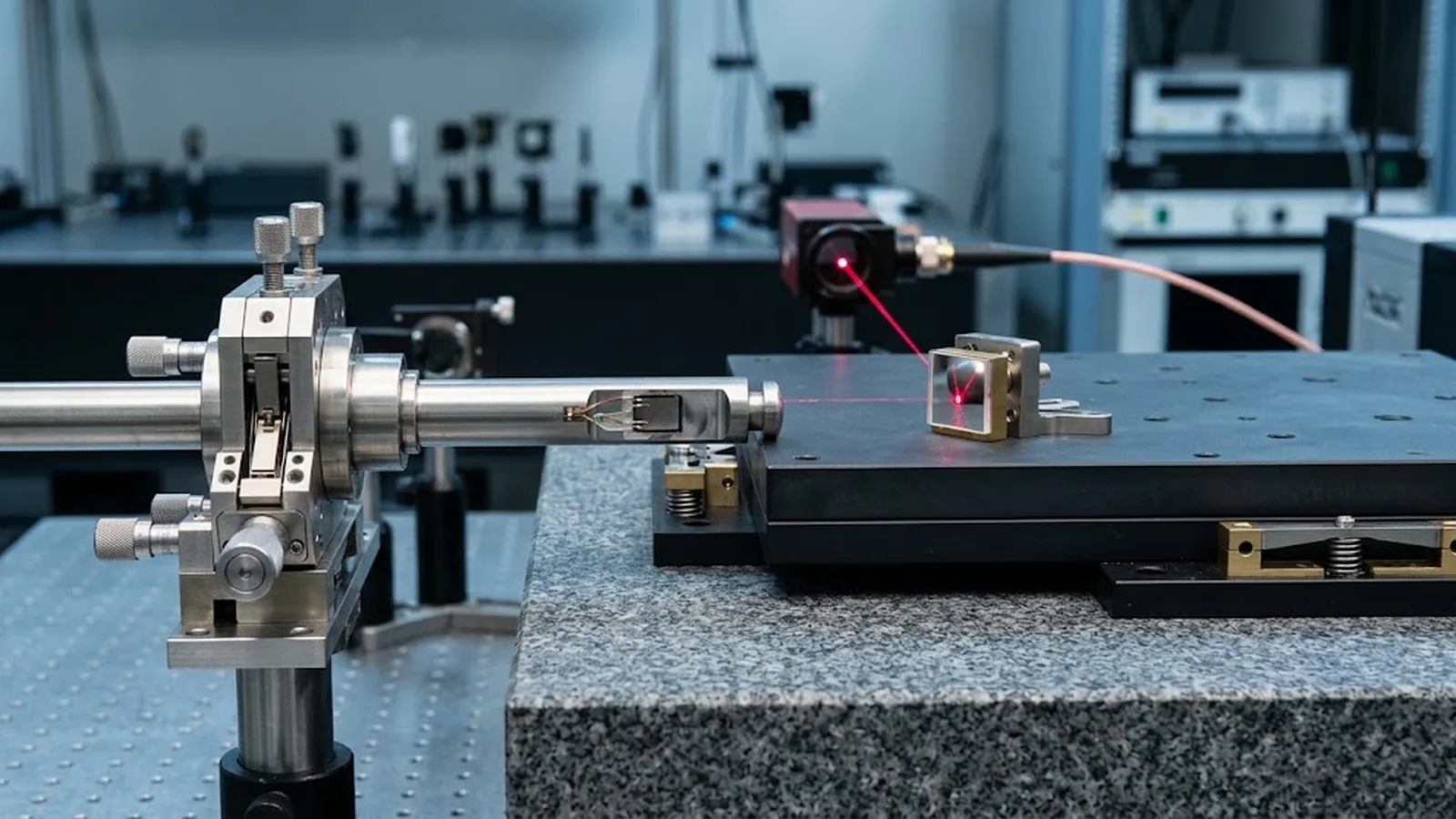
Static mapping is mechanically simple and unforgiving in its details. A calibrated force is applied at the substrate plane—through an instrumented push rod, a deadweight, or a controlled actuator—while displacement of the exposure-to-substrate loop is read by laser interferometers, capacitance probes against a reference, or in favorable geometries by the machine's own measurement chain. The measurement must be taken at the loop endpoints that matter, not at convenient mounting pads, and the stage should be characterized at a grid of positions across the full travel in both axes, plus vertical load cases that represent chucking, focusing, and payload changes.
Two practical rules keep the map honest. First, repeat each load case in loading and unloading directions: elastic hysteresis and micro-slip in bolted joints and cable chains show up as a gap between the two branches, and that gap is real overlay error. Second, repeat at least the corner positions with the minimum and maximum specified substrate and with the chuck evacuated and vented, because payload compliance is part of the machine's behavior, not an externality. Where the encoder chain itself is used as the displacement sensor, the analyst must remember what it measures: position of the scale, not position of the substrate surface, and the difference between the two is exactly the structural term being mapped.
Dynamic compliance, servo bandwidth, and write-on-the-fly exposure
Static maps describe the structure at rest; exposure frequently does not happen at rest. In write-on-the-fly operation the stage scans continuously while the pattern engine fires, and the structure is excited by the drive's own force ripple, by acceleration profiles, and by any periodic disturbance at scan or drum frequency. At these frequencies the loop's response is governed by its resonances: below the first structural resonance the stage behaves roughly like the static spring the map measured, but near a resonance a small periodic force produces displacement out of all proportion to the static slope. This is why two machines with identical static stiffness can behave entirely differently at exposure velocity.
The dynamic map—measured by modal impact testing, a shaker, or identification from drive current and encoder error signals—therefore feeds two decisions. Servo bandwidth must sit comfortably below the structural resonances it is meant to fight through, or the controller will pump energy into the resonance instead of suppressing it. And exposure or scanning speed must be chosen so that excitation frequencies avoid the loop's sensitive regions, or the error must be accepted and compensated. For lithography stages this links structural measurement directly to velocity stability work: jitter observed at the encoder during scanning is often the structural loop being excited, and the remedy may be a mechanical fix or a speed choice rather than another round of servo tuning.
A map earns its keep only when its terms enter compensation and process decisions. Position-dependent compliance across travel can be tabulated and corrected as a position-dependent scale or grid correction, exactly as an interferometer-calibrated error map is applied; direction-dependent terms become direction-dependent corrections with a residual equal to the hysteresis branch gap; payload-dependent terms define the re-qualification requirement whenever the substrate format changes. Terms that are too variable to compensate—because they depend on unmonitored forces—are converted into mechanical requirements: stiffer brackets, relocated cable chains, or a redesign of the chuck interface.
The map also disciplines purchase and upgrade decisions. When a stage is evaluated for overlay-critical work, the map turns 'how rigid is it' from a datasheet comparison into answerable questions: what is the measured loop compliance at the field corners, how much does it change across travel, where are the first resonances relative to the intended scan speed, and what evidence exists that these numbers were measured at the substrate plane rather than inferred from the guide catalogue. On installed machines, re-measuring a handful of map points after any structural modification—new head, new chuck, rerouted cables—catches the migration of compliance terms before it appears as a drift in overlay performance.
Overlay errors that survive encoder calibration usually live in the structure: compliance that varies across travel, between directions, with payload, or with frequency. A rigidity map makes those variations measurable, and once measured they stop being mysteries—they become corrections with known residuals, servo and speed decisions with known margins, or mechanical requirements with a stated target.
The practice is compact and repeatable: measure force-to-displacement at the substrate plane across a grid of positions and the dominant load cases, capture the dynamic response where exposure happens at speed, route every mapped term into compensation or the error budget, and re-verify the key points after any structural change. A stage treated this way prints its structure deliberately rather than accidentally—and the rigidity map becomes the document that tells the next engineer why the grid looks the way it does.
Force-deflection data recorded at defined stage positions across travel, in X, Y, and vertical load cases, with applied force and measured displacement traceable to calibrated instruments
Frequency-response function of the structural loop at representative stage positions, showing resonances relevant to the servo bandwidth and write velocity
Overlay or grid mapping results before and after rigidity-based compensation, demonstrating the mapped terms account for the observed residuals
Substrate and payload dependence: deflection data repeated with the minimum and maximum specified substrate stack, including vacuum chuck state
Statement of environmental conditions during mapping, because structural behavior and measurement instruments both drift with temperature
FAQ
Questions engineers ask before selection.
Why doesn't a high-resolution encoder eliminate structural overlay error?
The encoder measures position where the scale is mounted. Structural compliance displaces the substrate surface or the optical axis relative to the scale under process and dynamic loads, so the feedback can read correctly while the printed geometry carries the deflection. Only a map of the structural loop—at the substrate plane—captures those terms.
How many positions do I need for a useful static rigidity map?
Enough to resolve the trend: as a minimum the field center, all four corners, and the midpoints of each edge, in both horizontal directions plus the dominant vertical load case, each measured in loading and unloading. If the resulting surface shows strong curvature, refine locally until the interpolation uncertainty is small against the overlay budget line.
Can I map rigidity using the machine's own encoder signals instead of external instruments?
Partially. Applying a known force and reading the encoder shows how the scale position responds, which is useful for servo and compensation work, but it cannot see deflection between the scale and the substrate surface—the exact term that matters most for overlay. External interferometer or probe measurements at the loop endpoints are required for the full structural loop.
What is the difference between static stiffness and dynamic compliance for exposure quality?
Static stiffness governs quasi-static errors: chucking deflection, payload sag, position-dependent scale error. Dynamic compliance governs what happens while things move: resonant amplification of drive ripple and acceleration forces, velocity-dependent error during scanning, and settling after moves. Both belong in the map because exposure exercises both regimes.
When should the rigidity map be re-measured?
After any change in the load path: new exposure head or autofocus hardware, different chuck or substrate format, rerouted cable chains, base or isolation changes, and after major service that involves structural joints. A short-form re-check at the corners and center, compared against the original map, is usually sufficient to detect migration.