
Synchronization architecture disclosure
How the pattern generator is clocked from the encoder: hardware position-triggered emission, encoder-follower timing or software interpolation, including latency from encoder sample to modulator output.
TECHNOLOGY / LITHOGRAPHY MOTION
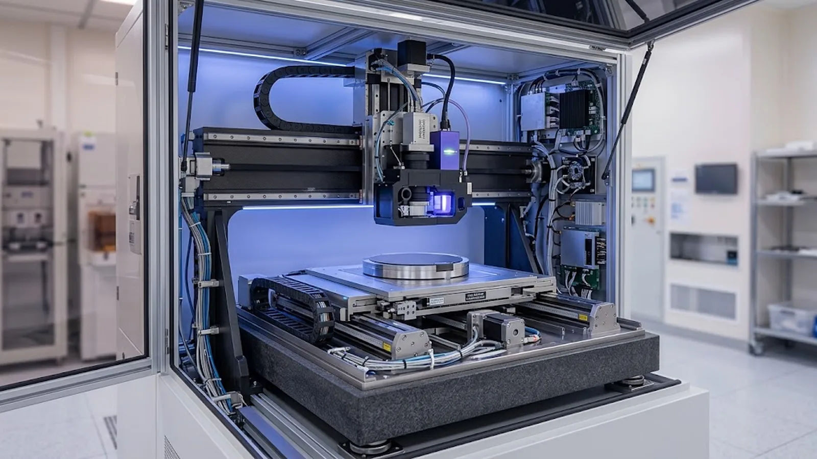
Two writing architectures place very different demands on position feedback. This guide compares write-on-the-fly and step-and-repeat direct-write lithography, explains how encoder synchronization works in each, and gives buyers the specification questions that separate the two modes on paper before they differ on the substrate.
Published
DIRECT ANSWER
Step-and-repeat lithography exposes while the stage is stationary: move, settle, expose, repeat. Write-on-the-fly lithography exposes while the stage is in continuous motion, with the pattern data stream synchronized to the stage's instantaneous position. The feedback requirement differs fundamentally: a step-and-repeat stage needs excellent settled accuracy and repeatability at each field, while a write-on-the-fly stage needs a position signal that is both accurate and available at high update rates during motion, because every micron of stage travel between position samples becomes a placement error in the written pattern.
In write-on-the-fly mode the optical encoder is effectively the master clock of the exposure: as the stage crosses each scale increment, the encoder reports position and the pattern generator emits the corresponding pixel or stroke data. The critical specifications are scale accuracy over the writing path, interpolation error at writing speed, encoder update latency versus exposure data timing, and velocity stability of the stage between encoder samples. Buyers should require the vendor's position-synchronization architecture, the encoder update rate used during writing, and field placement data measured with writing in motion, not only static stage specifications.
ENGINEERING CONTEXT
Vendor datasheets present both modes with similar headline numbers—resolution, minimum feature, field size—so the difference appears to be a throughput trade-off. In operation the modes fail differently. A step-and-repeat tool that writes dense fields slowly is at least predictable: errors appear as field placement offsets that overlay metrology can localize. A write-on-the-fly tool with a weak synchronization chain produces subtler defects: line ends misplaced at scan boundaries, stitch errors that vary with writing speed, pattern distortion that follows the stage's velocity profile and disappears in static verification. Because the defects depend on motion, they are invisible in the static accuracy tests most buyers know how to request.
Discuss your requirement ↗CRITICAL REQUIREMENTS
How the pattern generator is clocked from the encoder: hardware position-triggered emission, encoder-follower timing or software interpolation, including latency from encoder sample to modulator output.
Scale accuracy, interpolation error and signal quality specified at the velocities used during exposure, not only at rest or at low speed.
For step-and-repeat: settle time per field and the residual drift during exposure. For write-on-the-fly: velocity ripple over a field and its effect on dose and placement.
Measured field-to-field placement and intra-field distortion with writing in motion, at the throughput the buyer intends to run, on the buyer's substrate type.
BUYER MATRIX
Give every shortlisted supplier the same process definition and request configuration-specific proof.
| Aspect | Step-and-repeat (expose at rest) | Write-on-the-fly (expose in motion) |
|---|---|---|
| Exposure condition | Stage stationary and settled at each field | Stage in continuous motion across the field |
| Dominant encoder demand | Settled accuracy and repeatability at field positions | Accuracy and update rate during motion; position-triggered data emission |
| Failure signature | Field placement offsets; stitch errors at fixed boundaries | Speed-dependent placement and dose errors; line-end misplacement at scan boundaries |
| Verification method | Static field placement metrology | Dynamic tests: writing at production speed, stitch and overlay metrology |
| Typical advantage | Simple timing; tolerant of moderate encoder latency | Higher throughput on dense patterns; no settle time per field |
| Typical constraint | Settle time dominates cycle time on many small fields | Synchronization chain quality sets the pattern fidelity ceiling |
In a step-and-repeat tool, the stage carries the substrate to a field position, the servo settles, and the exposure proceeds while the mechanics are nominally still. Position feedback matters in two places: bringing the field to its commanded location, and holding it there against vibration and drift during the exposure. Accuracy is a settled property, and the encoder's dynamic behavior matters mainly through the servo loop, not through the exposure itself.
Write-on-the-fly inverts this. The stage never stops; the pattern is emitted in register with the moving substrate. Every element of the pattern must be placed at the moment the substrate passes the exposure zone, so the encoder's reading of instantaneous position is converted directly into pattern geometry. A timing skew between the position sample and the modulator output becomes a placement error; an encoder update that arrives late leaves the pattern generator guessing; velocity variation changes the effective dose per unit length. The encoder is no longer merely reporting position—it is pacing the exposure.
In a hardware-synchronized write-on-the-fly system, the encoder's incremental signal is processed into position samples that trigger or clock the pattern data path. The scale pitch sets the natural spatial sampling grid; interpolation multiplies it into finer position steps. The pattern generator maps each incoming data element to the position interval during which it should be exposed, and the modulator switches accordingly. The whole chain—scale, readhead, interpolation, synchronization electronics, data formatter, modulator—has a total latency, and latency that is constant can be compensated; latency that varies cannot.
This is why the quality of the synchronization matters as much as the encoder's datasheet accuracy. A high-resolution encoder with jittery interpolation produces pattern wobble no error map can remove, because the wobble happens within a single field at writing speed. Conversely, a modest-resolution encoder with a clean, deterministic timing chain can deliver excellent pattern fidelity. Buyers should ask vendors to describe the chain explicitly and to state which encoder configuration was used for the placement data they present.
Step-and-repeat errors concentrate at field boundaries: overlay metrology between fields shows placement offsets, and stitch quality at the boundary reflects the relative placement of adjacent fields. Because exposure happens at rest, dose is uniform within a field unless intensity or focus drifted. These errors are localizable with standard overlay tools, and corrective action—error mapping, settle tuning—follows familiar stage-qualification practice.
Write-on-the-fly errors follow the motion. Placement error grows along the scan direction where encoder latency or velocity ripple accumulates; dose varies with the instantaneous writing speed, so line width changes across fields written at different accelerations; line ends at scan reversals inherit the worst dynamic conditions. Detection therefore requires dynamic tests: write test patterns at production speed and inspect stitch, placement and linewidth along and across the scan direction, then repeat at reduced speed—an error that shrinks with speed points at the synchronization chain rather than at static geometry.
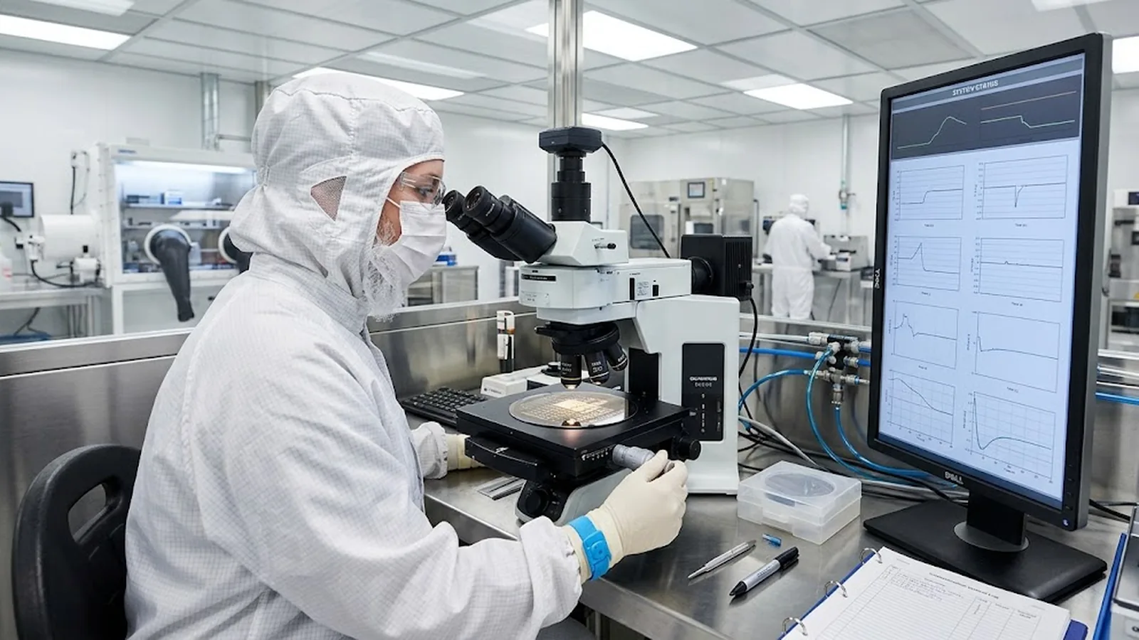
The economics follow from the pattern structure. Workloads with many small, dense fields—photonic waveguide arrays, sensor grids, memory-like arrays—are dominated by settle time in step-and-repeat mode, and write-on-the-fly can cut writing time substantially because the stage never stops. Workloads with sparse, large-area geometry, or processes where per-field alignment and focusing are critical, often run as well or better with the simpler timing of step-and-repeat, and the same tool may support both modes with the encoder synchronization chain engaged only when writing in motion.
The deciding evidence is dynamic, not nominal. Ask each candidate vendor for: writing time on your actual layout class, placement and stitch metrology taken with writing in motion at the quoted throughput, and the encoder configuration and synchronization latency behind those numbers. A tool that documents these cleanly can be qualified for either mode; a tool that answers only with static stage specifications should be treated as unproven for write-on-the-fly regardless of its datasheet resolution.
Reduce the mode decision to verifiable questions. For write-on-the-fly: what is the encoder update rate and total synchronization latency during writing, is the latency constant, and what velocity range does the tool write over with placement held within specification? For step-and-repeat: what is the settle time per field at the field size and acceleration you will run, and what residual position drift occurs during a typical exposure? In both modes: which scale accuracy grade and interpolation configuration is installed, and can the vendor supply placement data measured with the same configuration?
Finally, align the acceptance test with the mode. A factory acceptance test for a write-on-the-fly tool must include patterns written in motion at production settings and inspected for stitch, placement and linewidth—static positioning verification alone will pass a tool whose dynamic synchronization is marginal. Agreeing on this before purchase costs nothing; discovering it after installation costs a tool.
CONCLUSION
Step-and-repeat exposes a settled stage and lives on static accuracy, repeatability and settle time. Write-on-the-fly exposes a moving stage and lives on the quality of the chain that turns encoder position into pattern data: spatial sampling, interpolation cleanliness, constant latency and velocity stability. The modes share an encoder but not a specification.
Qualify the mode you will run with evidence generated the way you will run it—placement and stitch measured with writing in motion, at production speed, with the installed encoder configuration. Tools documented this way deliver pattern fidelity as a specifiable property instead of a throughput surprise.
EVIDENCE CHECKLIST
FAQ
A writing mode in which exposure occurs while the substrate stage moves continuously, with pattern data synchronized to the stage's instantaneous position from the encoder feedback. It removes per-field settle time and is mainly used for dense patterns where step-and-repeat settle time dominates writing time.
Because the encoder effectively paces the exposure: each position sample determines where pattern elements are placed on the moving substrate. Encoder update rate, interpolation quality at speed and constant synchronization latency all convert directly into pattern placement and dose, whereas in step-and-repeat mode the encoder mainly supports settled positioning.
It improves writing time most for many small dense fields, where settle time per field dominates. For sparse layouts or processes needing per-field alignment and autofocus, the gain may be marginal and the simpler timing of step-and-repeat can be preferable. The comparison should be made on the actual layout and process.
Require dynamic acceptance evidence: test patterns written in motion at production speed on your substrate type, inspected for stitch error, field placement and linewidth along and across the scan direction, with the writing repeated at reduced speed to confirm error behavior. Static positioning verification alone does not exercise the synchronization chain.
Many direct-write platforms support both, engaging the encoder synchronization chain only when writing in motion. Confirm which mode the quoted placement and throughput figures were measured in, and which encoder configuration was installed, because performance can differ between modes on the same machine.
Scale accuracy grade, interpolation configuration, update rate and synchronization latency during writing, velocity range over which placement is held, and the measurement method behind any placement figures. SENFU can review these requirements for stage and encoder integration in direct-write lithography tools.
AUTHORITATIVE SOURCES
TECHNICAL REVIEW
Send the application, critical parameters and any drawing or process information available.
Discuss your application ↗