
Bidirectional measurement
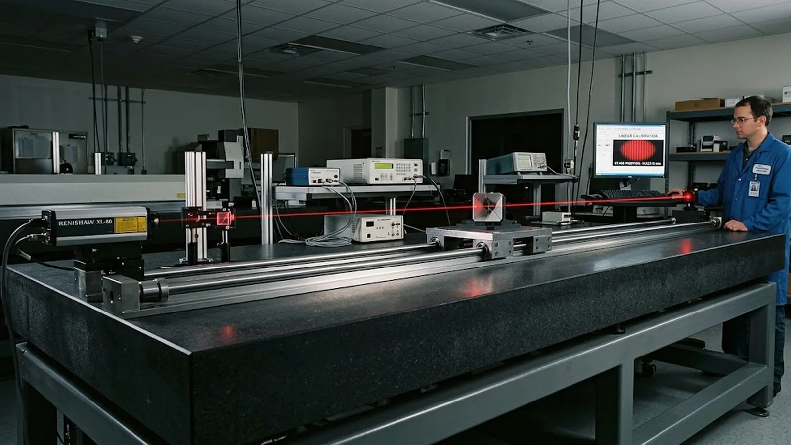
A traceable reference—typically a laser interferometer—recording both approach directions at each target across the travel.
TECHNOLOGY / STAGE METROLOGY
What reversal error is, why a unidirectional error map hides it, how bidirectional laser interferometer measurement quantifies it, and what compensation and design measures actually reduce it.
Published
DIRECT ANSWER
Reversal error is the difference between the positions an axis reads when a target point is approached from opposite directions. Its systematic part comes from mechanical play and lost motion in the drive train—backlash in gears or screws, compliance in couplings and bearings—and a hysteresis component from friction and elastic deformation that releases differently on each side of the approach. Encoder suppliers specify a small reversal error for the feedback itself, from the mechanical coupling between scale and readhead; the axis-level figure is usually much larger and is dominated by the machine mechanics.
Reversal error is only visible to a bidirectional measurement. A test that approaches every target from one direction—like many unidirectional error maps—reports repeatability that looks excellent while the step that appears on every direction change goes unrecorded. Quantification follows the bidirectional logic of ISO 230-2: approach each target from both directions, record both position readings, and evaluate the systematic reversal deviation together with bidirectional repeatability. Compensation can then remove the systematic portion—through backlash compensation or bidirectional error tables—but friction hysteresis that varies with load and dwell behaves non-deterministically and cannot be fully compensated away.
ENGINEERING CONTEXT
Machine builders routinely qualify an axis with a unidirectional positioning test, receive a flattering repeatability number, and then see contouring errors or dimensional scatter on parts that involve direction changes. The cause is reversal error: the axis settles to different positions depending on the approach side. Because the error is real position uncertainty at every reversal, it belongs in the accuracy budget like scale error and Abbe error—yet it is invisible to a one-way map and easy to miss until it appears on the workpiece. The work is to measure it bidirectionally, separate the systematic backlash from load-dependent hysteresis, and then decide what compensation and what mechanical measures will each remove.
Discuss your requirement ↗CRITICAL REQUIREMENTS
A traceable reference—typically a laser interferometer—recording both approach directions at each target across the travel.
Measurements taken with the actual moving mass and tool offset, at traverse rates and dwell times similar to production.
Analysis that distinguishes constant mechanical backlash from friction hysteresis and random scatter.
Controller support for backlash compensation or bidirectional multipoint tables, with defined verification after entry.
BUYER MATRIX
Give every shortlisted supplier the same process definition and request configuration-specific proof.
| Aspect | Unidirectional error map | Bidirectional error map | Mechanical mitigation |
|---|---|---|---|
| What it shows | Systematic error along one approach direction only | Both approach directions and the gap between them | Reduces the error source instead of reporting it |
| Reversal error visibility | Invisible—appears only on the workpiece | Directly measured at every target | Reduced by preloaded drives and stiff couplings |
| Compensation fit | Serves one-direction operation | Feeds backlash values or bidirectional tables | Minimizes what remains to compensate |
| Residual uncertainty | Full reversal step unknown | Hysteresis scatter remains around the systematic value | Wear can reopen play over time |
| Typical use | Quick setup checks | Machine qualification and error budgeting | Design and rebuild of precision axes |
The axis-level reversal error is the sum of contributions stacked along the drive train. Backlash in gear stages, ball screw nuts or rack-and-pinion systems contributes a roughly constant lost motion. Compliance in couplings, bearings and the bracket between scale and workpoint converts drive torque into elastic deflection, which releases on direction change. Friction adds hysteresis: the axis stops at a slightly different place depending on how the friction force relaxes, and this component varies with load, speed and dwell time rather than holding a fixed value.
The feedback loop contributes its own, usually much smaller, term. A scale and readhead connected through the mounting mechanics exhibit a reversal error of their own—the encoder datasheet states it typically in the low micrometer range or below, as a fraction of the system's total uncertainty. When an axis shows a reversal step of several micrometers, the dominant source is almost always the mechanical transmission, not the encoder. That diagnosis matters because the fixes are different: encoder-side reversal is addressed by selection and mounting, mechanical reversal by preload design and compensation.
The measurement follows the bidirectional logic standardized for machine tool positioning tests in ISO 230-2. A laser interferometer or equivalent traceable reference records the axis position as each target is approached from the negative direction and again from the positive direction, across the full travel, in several cycles. At each target the difference between the two mean approach positions is the systematic reversal deviation, and the spread of the individual readings on each side gives the bidirectional repeatability.
Two disciplines make the result trustworthy. First, approach each target with a defined overshoot so the measurement does not inherit the previous direction's friction state; rolling to a stop from one side and reading is not a reversal measurement. Second, hold the load condition constant and representative: moving mass, tool or fixture offset, and clamp state all change the elastic and frictional components, so a no-load figure does not describe the working machine. Repeating the cycles also separates the systematic gap from random scatter—large scatter on one or both sides signals hysteresis that compensation will handle poorly.
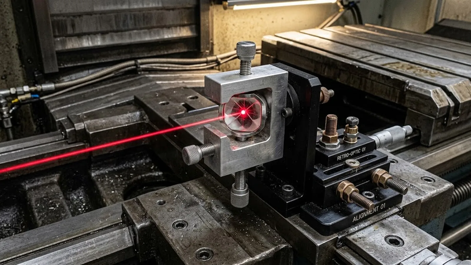
The systematic part of the reversal step is compensable. Machine controls offer backlash compensation that applies a direction-dependent offset on every reversal, and many support bidirectional error tables that hold separate correction values for each approach direction across the stroke. Entered after a bidirectional measurement and verified with a second run, these functions remove the repeatable portion of the step and can improve reversal behavior on a healthy axis substantially.
What remains is the hysteresis that does not repeat: friction-induced scatter that changes with load, speed, dwell and temperature. Compensation can only store one number or one curve per condition it was measured under; when the real machine varies around that condition, the residual appears as bidirectional repeatability spread. This is why the measurement's scatter analysis matters before compensation is planned—if the systematic gap is small but the scatter is large, the economical fix is mechanical, not a table.
Compensation also has a configuration lifetime like any error map. Preload wear, bearing changes and mechanical adjustments reopen or shift the play, so reversal behavior should be re-verified on a schedule and after any transmission service.
For machines still in design, reducing reversal at the source is cheaper than compensating it. Preloaded nut systems, preloaded or gearless drives, stiff short couplings and rigid scale mounting brackets remove the play and the compliance that create the step in the first place. Measuring the feedback at the workpoint with small Abbe offsets keeps the elastic contributions from multiplying into position error, and drive tuning with sufficient bandwidth holds the axis against friction transients at the reversal.
The encoder's role in this lever set is to keep the measurement side from adding to the problem: a small specified encoder reversal error, rigid mechanical coupling between scale and structure, and signal quality that stays stable through direction changes. The remaining axis-level reversal is then a transmission property to be measured, budgeted and either designed out or compensated deliberately.
SENFU treats reversal error as a budget line, not a surprise. For axis projects, the useful conversation covers the motion profile and its direction changes, the load condition under which reversal must hold, the transmission concept and the encoder's specified reversal error and mounting stiffness. From there, the bidirectional measurement plan and the compensation approach can be defined together with the machine builder.
The evidence to request is concrete: the encoder-side reversal error figure for the configured feedback, the scale mounting stiffness, and the bidirectional positioning results—including systematic reversal deviation and bidirectional repeatability—measured under representative load. Ask that the acceptance measurement be bidirectional even when the process appears one-directional, because real machines change direction more often than the cycle diagram suggests.
Submit the axis requirement through the application form and SENFU can review the feedback configuration and the reversal-related evidence needed before the machine is accepted.
CONCLUSION
Reversal error is the axis's direction-dependent position gap: systematic lost motion from the transmission plus load-dependent hysteresis, with a small contribution from the feedback itself. It stays invisible to unidirectional testing and surfaces on the workpiece at every direction change, so it must be measured bidirectionally and put into the accuracy budget deliberately.
Compensation removes the repeatable portion through backlash values or bidirectional tables; scatter and load dependence remain and are the cue for mechanical measures—preload, stiffness, small Abbe offsets and servo tuning. With a bidirectional acceptance measurement and periodic re-verification, reversal becomes a managed number instead of an intermittent quality problem.
SOLUTION ROUTES
EVIDENCE CHECKLIST
FAQ
Backlash is the mechanical lost motion in the drive train—gear or nut play—and is usually the systematic, repeatable part of reversal error. Reversal error is the total measured gap between approach directions, which includes backlash plus friction hysteresis, elastic release and the encoder's own reversal contribution.
A unidirectional test approaches every target from the same side, so the approach-side offset is constant and absorbed into the systematic error curve. The step that appears only on direction change is never sampled, and the reported repeatability describes only one-way behavior.
With a bidirectional positioning test using a traceable reference such as a laser interferometer: each target is approached from both directions with defined overshoot, over several cycles. The difference between the two approach-side means gives the systematic reversal deviation, and the reading spread gives bidirectional repeatability.
It removes the systematic, repeatable portion—a constant play or a direction-dependent curve measured under defined conditions. Friction hysteresis that varies with load, speed and dwell does not repeat precisely enough to compensate and remains as bidirectional scatter; large scatter calls for mechanical measures instead of a denser table.
Yes, but usually a small one. The scale-to-readhead mounting and scanning mechanics have a specified reversal error, typically far below the axis-level figure. When the measured reversal step is large, the transmission is the dominant source, and the encoder specification serves as the floor the mechanics add on top of.
Send the axis and transmission concept, the motion profile with direction changes, the load condition under which reversal must hold, and the encoder configuration. SENFU can help define the bidirectional measurement plan and the encoder-side evidence for the budget.
AUTHORITATIVE SOURCES
TECHNICAL REVIEW
Send the application, critical parameters and any drawing or process information available.
Discuss your application ↗