Optical Encoder Installation: The Mechanical Tolerances That Decide Whether the Datasheet Accuracy Survives
An optical encoder delivers its datasheet accuracy only inside the mechanical tolerance window its installation specifies. This guide sets out the tolerances that matter—mounting surface condition, scale parallelism, air gap, fastening torque, thermal compatibility and Abbe offset—how to verify each one during machine build, and what the axis does when each tolerance is violated.
Published
DIRECT ANSWER
What should a buyer prioritize?
The accuracy printed on an optical encoder datasheet is a system specification, not a component one: it holds only when the installation meets the supplier's mechanical tolerances—mounting surface flatness and finish, scale-to-guide parallelism within fractions of the signal period, the working air gap held across full travel and temperature, fasteners torqued to specification, and a thermal and Abbe geometry the machine design has actually chosen. Miss any of these and the axis quietly inherits error sources that no amount of interpolation or servo tuning can remove.
Treating installation tolerances as part of the machine's error budget—each with an owner, a verification method, and a written reading in the build record—is what separates an axis that measures its mechanics honestly from one that produces position errors, count faults, and drift complaints for the rest of its service life.
ENGINEERING CONTEXT
The decision starts with the real constraint.
When a precision axis fails to reach its specified accuracy at commissioning, the investigation usually starts at the controller and ends at the scale—and more often than anyone admits, the root cause sits in the hour the encoder was installed. An optical encoder is a measuring instrument bolted to a structure, and every deviation of that structure from the supplier's installation drawing becomes part of the measurement: a mounting surface that is flat to the eye but not to the tolerance, bowing the scale over its length; screws tightened unevenly that bend the scale into a cycle error; an air gap set once at room temperature that closes under thermal drift; a bracket chosen for convenience that puts the measuring line millimetres away from the process point. None of these produce a fault message: the encoder counts cleanly, and the machine is simply less accurate than the sum of its parts. Machine builders and integrators who treat installation tolerances as engineering deliverables—specified, verified, and recorded—commission their axes once; teams that treat them as assembly conventions repeat the same troubleshooting cycle on every new build.
Supplier tolerance table on the installation drawing
The encoder datasheet's installation section—flatness, parallelism, air gap, torque values, gap variation limits—transcribed onto the machine's own installation drawing, not left to the assembler's interpretation.
02
Qualified mounting surfaces
Scale and readhead datum surfaces verified for flatness, finish, and parallelism to the machine's guide line before assembly, with rework authority defined when a surface arrives out of tolerance.
03
Fastening and stress specification
Fastener sizes, torque values and sequence, threadlocker grade where specified, and an adhesive or clamping design that does not introduce bending stress into the scale.
04
Instrumented verification at build
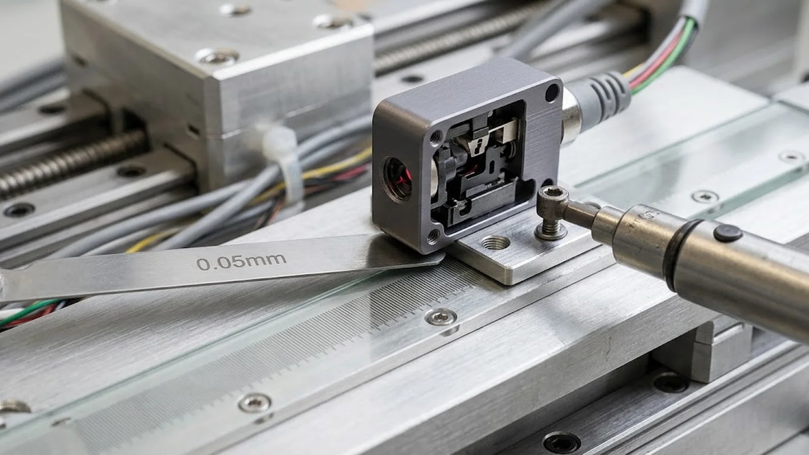
Dial indicators, feeler gauges or optical gap tools, and a torque wrench as standard build equipment, with readings recorded in the build file against the tolerance table.
BUYER MATRIX
Compare evidence, not feature labels.
Give every shortlisted supplier the same process definition and request configuration-specific proof.
The installation tolerances that decide encoder accuracy — where each one is specified, verified, and what it costs when violated
Interface tolerance
Typical specification source
Verification at build
Symptom when violated
Mounting surface flatness and finish
Encoder installation drawing (often sub-0.01 mm over scale length)
Straightedge, dial indicator on granite plate or in situ, surface finish comparison
Scale bowed by fastening; position error that repeats with the bow's period over travel
Scale-to-guide parallelism (pitch, roll, yaw)
Fractions of the signal period; often 0.05–0.2 mm/m depending on pitch
Dial indicator swept along the scale against the guide datum
Signal amplitude modulation along travel; interpolation error growth and lost counts at worst positions
Working air gap and gap variation
Supplier gap window with a variation limit across travel and over temperature
Feeler gauges or dedicated gap tool at both ends and middle of travel
Reduced signal margin; intermittent count faults under vibration or thermal drift
Fastener torque and sequence
Torque table on the installation drawing; threadlocker grade where specified
Calibrated torque wrench, documented sequence
Bending stress frozen into the scale; cycle error or long-term drift as stress relaxes
Thermal compatibility (scale CTE vs base)
Scale material selection guidance relative to machine base material
Material pairing review at design stage; warm-up drift test at commissioning
Ambient temperature swings converted directly into position error
Abbe offset and bracket geometry
Machine design: measuring line placement relative to the process point
Design review of bracket drawing; as-built measurement of offset
Guide angular errors amplified into positioning error at the workpiece
Installation tolerances are part of the accuracy specification, not assembly etiquette
Encoder datasheets state accuracy in two layers that procurement teams sometimes conflate. The scale's grade—its intrinsic line-error envelope—is a property of the component. The system accuracy the axis actually achieves is that grade plus everything the installation adds: the geometry of the mounting surfaces, the alignment of the scale to the guide line, the stability of the air gap, the stress state frozen in by the fasteners, and the thermal behaviour of the material pair. That layer is entirely the machine builder's, and it is where most of the gap between datasheet promise and commissioning reality is created. A 1 µm-grade scale fastened to a surface that bows it a few microns over its length delivers a 1 µm-grade measurement of a bow, not of the stage position.
This is why the tolerance table belongs on the machine's installation drawing, next to the GD&T of the surfaces that carry the encoder—not in a supplier datasheet the assembler may never read. Each tolerance needs a named verification method and a place in the build record. The error modes behind each tolerance, with their diagnostic signatures, are catalogued in the guide to linear encoder installation alignment errors.
The mounting interface: flatness, finish, and the surface the scale actually sees
Everything begins with the datum surfaces the scale and readhead bolt onto. Flatness is the critical property: a scale fastened to a surface with a convex or concave deviation takes that shape permanently, converting an assembly condition into a fixed position error pattern. Verification is deliberately low-tech—a dial indicator and a known reference—but it must happen before assembly, not be inferred from the machining certificate—handling and stress relief move surfaces. Surface finish matters for a second reason: it determines whether the scale seats at the same points after every removal, which makes the installation reproducible through service.
Parallelism between the scale mounting line and the machine's guide line is the second interface property, specified in fractions of the signal period: as the readhead travels, pitch, roll, and yaw deviations of the scale modulate the signal amplitude and phase the interpolation receives. Within tolerance, the modulation stays inside the interpolation margin; outside it, the axis develops position-dependent signal quality—clean counts at one end of travel, degraded interpolation at the other—that is miserable to diagnose after the machine is closed up. Measuring it takes a dial-indicator sweep along the scale against the guide datum.
Air gap and fastening: the two tolerances with the narrowest windows
The working air gap between readhead and scale is the smallest mechanical dimension in the drive train, with the least margin for assembly variation. Suppliers specify both a nominal window—typically fractions of a millimetre—and a variation limit across full travel, because residual parallelism error and carriage deflection change the gap along the stroke. The gap must therefore be set at both ends and the middle of travel, at operating temperature. A gap set once at room temperature on a machine that runs warm closes or opens with thermal drift, and the symptom—falling signal margin, intermittent count loss under vibration—appears weeks later with no mechanical suspect. The gap window, variation limits, and setting procedure are set out step by step in the guide to optical encoder air gap and clearance setup.
Fastening is the twin trap. Scale fasteners tightened unevenly, or to the wrong torque, put bending stress directly into the scale body—and a stressed scale carries a frozen-in geometry error that relaxation will slowly change over the first months of service. The specification is mundane and non-negotiable: torque values, a centre-outward sequence on long scales, threadlocker grade where the supplier calls for it, and a calibrated wrench rather than assembler feel. None of it is difficult; all of it is invisible in the finished machine—which is why it must live in the build record.
Thermal and structural tolerances: the errors the build cannot see
Two installation decisions are made at the design stage but paid for at every temperature change. The first is scale material selection relative to the machine base: a scale whose coefficient of expansion differs from the structure it measures converts ambient drift into counted position error at a rate set by the mismatch. The pairing is a design choice—substrate material, mounting stiffness, compensation strategy—and should be made against the machine's environment, not defaulted to the catalogue standard. The mechanics of the mismatch and the mounting strategies that manage it are treated in the guide to optical encoder scale CTE mismatch mounting.
The second is the placement of the measuring line. Abbe's principle is an installation tolerance like any other: the distance between the measuring line and the process point multiplies the guides' angular errors—pitch, yaw, roll—into positioning error at the workpiece. The bracket that carries the readhead fixes that distance permanently, so bracket design is where the Abbe offset is either engineered small or accidentally inherited from whatever geometry was convenient to bolt. Bracket stiffness belongs to the same review, because a compliant bracket turns vibration and acceleration into readhead displacement the encoder faithfully reports as stage motion.
Verification: closing the installation against the tolerance table
An installation is complete when its measured values exist on paper, not when the readhead produces a stable count. The verification set is short and cheap: surface flatness and parallelism readings before assembly, air gap readings at the defined travel positions, torque values as applied, and the as-built Abbe offset. Recording these turns every later conversation—commissioning, service calls, retrofits—from archaeology into comparison.
The record earns its keep at commissioning, where installation readings and positioning test results should be filed together. When an axis verifies inside its error budget, the installation record shows why; when it does not, the readings point at the deviation—gap variation at mid-stroke, a parallelism outlier at one end of travel—instead of a generic loop of signal checks. Builders who pair the two files localize a positioning anomaly to its installation root cause in a single meeting.
CONCLUSION
The datasheet accuracy is delivered by the installation, not the part.
An optical encoder's specified accuracy survives machine build only inside the tolerance window its installation drawing defines: flat and parallel mounting surfaces, an air gap held across travel and temperature, fasteners torqued into a stress-free scale, a thermal pairing chosen for the machine's environment, and a measuring line placed with the Abbe offset in mind. Every one of these is verifiable with basic shop instruments during assembly, and every one becomes an untraceable positioning error if it is skipped.
Specify each tolerance on the machine's own drawings, verify each with a named instrument and a recorded reading, and file the installation record beside the commissioning test. The encoder will then do what the datasheet promised—and keep doing it through service, retrofits, and the next engineer's troubleshooting session.
Tolerance table: supplier installation limits for flatness, parallelism, air gap, gap variation and torque, as annotated on the machine installation drawing
As-built readings: measured surface flatness, parallelism and air gap values recorded per axis in the build file, with instrument identification
Fastening record: torque values applied and sequence used for scale and readhead fasteners
Commissioning linkage: installation readings paired with the axis's positioning verification results, so tolerance excursions can be traced to performance
FAQ
Questions engineers ask before selection.
How flat does a scale mounting surface actually need to be?
Follow the supplier's installation drawing, which typically specifies a flatness envelope over the full scale length well below the scale's accuracy grade—often in the range of hundredths of a millimetre for longer scales. The critical failure is fastening a scale onto a deviating surface, which bows it permanently; verify the surface with a dial indicator before assembly rather than trusting the machining certificate.
Can I set the encoder air gap once at mid-travel and move on?
No. The gap must be verified at both ends and the middle of travel because residual parallelism error and carriage deflection change it along the stroke, and it should be set at operating temperature where the machine's thermal growth is representative. A single-point setting hides exactly the gap variation that later appears as position-dependent signal degradation.
Why does fastener torque matter so much on encoder scales?
Uneven or excessive torque bends the scale, freezing a geometry error into the measurement and creating long-term drift as the stress relaxes. Use the supplier's torque values and sequence—typically centre-outward on long scales—with a calibrated wrench, and record what was applied.
Does scale material choice really affect positioning accuracy?
Yes, through thermal behaviour. A scale with a coefficient of expansion mismatched to the machine base converts ambient temperature changes into position error proportional to the mismatch and the scale length. Pair the scale material to the base structure and the machine's environment at design time, and verify with a warm-up drift test at commissioning.
We are seeing degraded signal quality at one end of travel only. What should we check first?
Check scale-to-guide parallelism and gap variation along the stroke—both are classic causes of position-dependent signal amplitude changes. Sweep a dial indicator along the scale against the guide datum and re-measure the gap at that end of travel; the reading usually identifies the offender before any electronics are suspected.