
CTE values stated for both sides
The scale substrate and the actual mounting surface (not the nominal machine frame) have documented expansion coefficients, and the differential over the working range is calculated before ordering.
TECHNOLOGY / ENCODER MECHANICAL INTEGRATION
An optical linear encoder is only as accurate as the thermal pair it forms with the surface it is mounted to. This guide explains how coefficient-of-thermal-expansion mismatch between scale substrate and mounting surface produces strain, bowing and drift, and how to choose scale material, mounting method and installation temperature as one engineered decision.
Published
DIRECT ANSWER
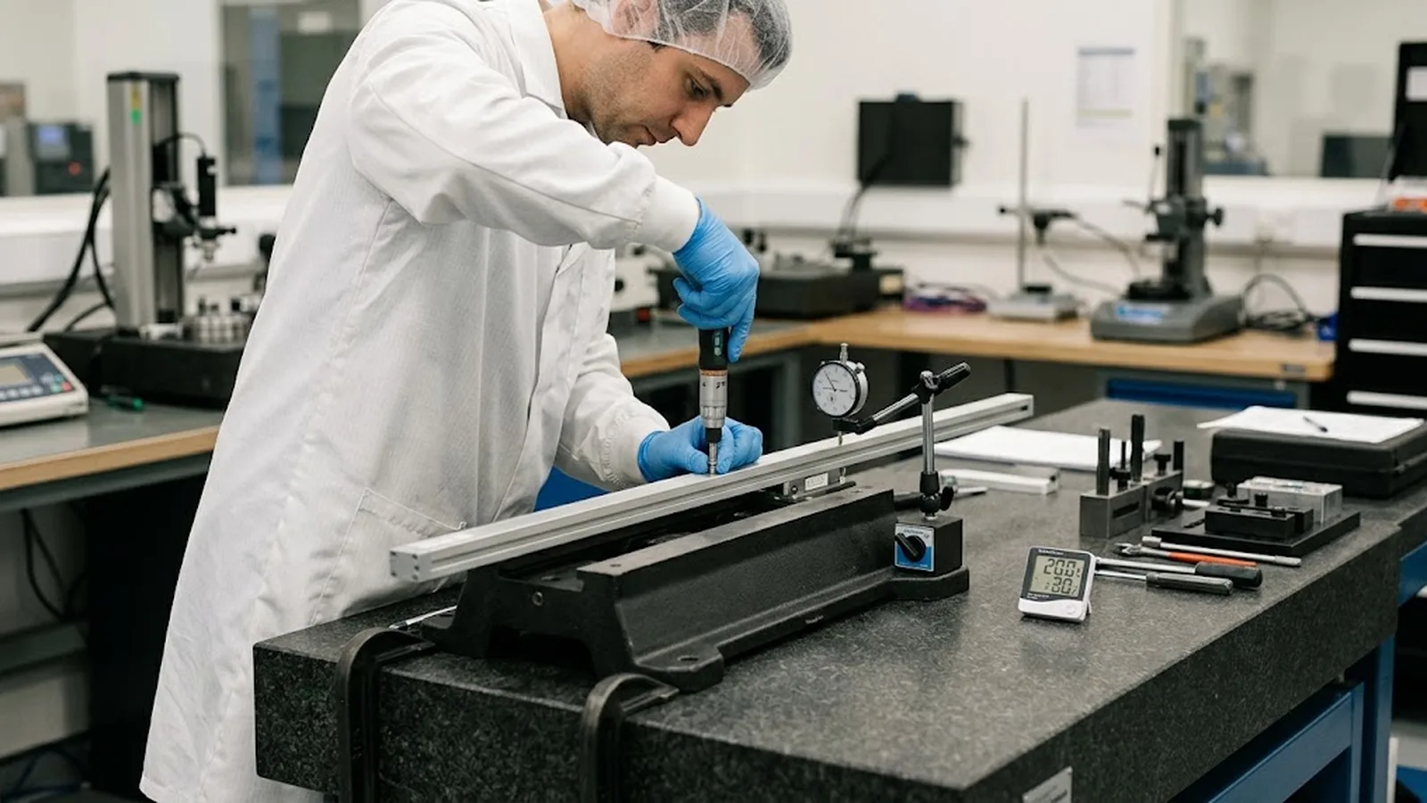
Every linear optical encoder measures position between a scale and a readhead, but the scale is bonded or clamped to a machine surface with its own coefficient of thermal expansion (CTE). When the two materials expand at different rates, a temperature change forces the scale into tension or compression and, if its ends are constrained, bows it into an arc. The encoder faithfully reports all of it: the scale's own strain appears as a length error, and the bow moves the graduations out of the readhead's measuring plane. For a 500 mm glass scale on a steel table, a 10 K change against roughly 12 ppm/K of mismatch is a 60 micrometer disagreement—several times the accuracy grade printed on the datasheet.
The fix is a matched-pair design decision, not an afterthought: choose scale substrate and mounting surface with similar expansion coefficients, select a mounting method that lets the scale follow its substrate instead of fighting it, install at a defined reference temperature, and verify the pair with a warm-up drift test before the machine is qualified.
ENGINEERING CONTEXT
Encoder selection is usually finished at the accuracy grade and resolution line of a datasheet, and the mechanical integration is delegated to whoever fits the scale during assembly. The thermal pair is then decided implicitly: a glass scale goes onto a steel casting, an aluminum bracket bridges the two, and nobody records the differential expansion the combination implies. The error does not appear at commissioning, because commissioning happens at a stable temperature after warm-up. It appears weeks later as unexplained positioning drift when the workshop warms by a few degrees, or as repeatability that depends on how long the machine has been running. Because the symptom looks like servo behavior or structural drift, teams tune loops and re-scrape surfaces while the root cause is a scale in tension on a substrate that expands faster than it does.
Discuss your requirement ↗CRITICAL REQUIREMENTS
The scale substrate and the actual mounting surface (not the nominal machine frame) have documented expansion coefficients, and the differential over the working range is calculated before ordering.
Tape, epoxy or clip mounting is chosen so the scale can strain with its substrate; long scales use end-free or controlled-end constraint rather than a fastener in every hole.
Installation and zero-setting happen at a documented reference temperature with the substrate thermally soaked, so the mechanical zero is meaningful across the temperature range.
A warm-up and temperature-sweep test measures axis position against a thermally insensitive reference, proving the drift contribution fits the machine's error budget.
BUYER MATRIX
Give every shortlisted supplier the same process definition and request configuration-specific proof.
| Combination | Approx. differential CTE | Typical signature | Primary mitigation |
|---|---|---|---|
| Glass scale on steel machine table | ~0–4 ppm/K with matched glass grade (glass ~3–13) | Small residual drift if grade matched; bow error if ends constrained | State the glass grade at ordering; tape or clip mounting |
| Glass scale on granite base | ~5 ppm/K (granite ~5–8) | Mismatch masked until ambient changes fully soak in | Match glass grade to the granite value; allow long soak before zeroing |
| Glass scale on aluminum structure | ~10 ppm/K (aluminum ~23) | Large, fast-cycling differential; drift appears within minutes of motion | Steel-tape scale preferred; otherwise slotted clips and compensation |
| Steel tape scale on steel substrate | Near zero | Minimal differential; tape follows the substrate structurally and thermally | Standard choice for long axes; verify tape tension specification |
| Invar or glass-ceramic scale on steel | 3–10 ppm/K (compensated direction) | Scale nearly static while the machine moves; error dominated by structure | Use where scale stability is the budget priority; accept cost premium |
A linear encoder does not measure the position of the tool; it measures the position of the readhead relative to the scale, so whatever happens to the scale is indistinguishable from real motion. When the scale substrate and the surface beneath it have different expansion coefficients, a temperature change creates a strain the scale cannot avoid absorbing: bonded scales stretch or compress, clamped scales bow between their fixing points. Both effects convert directly into position error, scaling linearly with temperature change and differential CTE—no servo, filter or interpolation setting can remove them, because the encoder itself is the source.
The magnitude is easy to underestimate because the numbers look small. A differential of 10 ppm/K over 1 K on a 300 mm scale is 3 micrometers, comfortably inside most accuracy grades. But workshops see 5 to 15 K between a cold morning start and an afternoon fully soaked, and the error accumulates along the whole measuring length: 600 mm of scale at 12 ppm/K over 10 K is 72 micrometers of disagreement between scale and substrate. Against a typical glass scale grade of ±5 micrometers, the mounting decision dominates installed accuracy by an order of magnitude.
The choice only works if it is made against the real mounting surface. Glass grades, steel tapes, Invar and glass ceramics exist precisely because the substrate can be matched to the application; the scale material guide covers each substrate family in detail, and the thermal-drift guide explains how scale behavior combines with the machine's own warm-up into the axis's total drift budget.
Mismatched expansion attacks the scale in three ways, each with a different fingerprint. The first is uniform strain: if the scale is continuously bonded to a faster-expanding substrate, it is put into tension proportionally to the differential and its graduations move apart. The encoder reads this as a true length change—the graduations really did move—and the error is proportional to position along the axis, so it masquerades as a linearity error that worsens toward stroke ends.
The second is bowing. Held at discrete points—clips at the ends, or fasteners at intervals—the unconstrained portions arch as the differential grows. A bowed scale no longer lies in the readhead's measuring plane: the readhead sees graduations at varying angle and height, which shortens the effective pitch and adds a sinusoidal error component tied to the bow geometry. Severe bow also perturbs air-gap and signal balance, so bad cases surface first as degraded signal quality rather than as an obvious position error.
The third is the gradient case, which needs no mismatch at all: a heat source on one side of the machine—motor, spindle, sunload—creates a temperature difference between scale and substrate even when their CTEs are identical. Gradients are transient and asymmetric, which makes them hardest to compensate and the most common reason a machine reproduces perfectly at steady state but scatters after startup. Telling the three mechanisms apart requires correlating position error with temperature over time, not a static laser measurement at soak.
The matching decision is made between two materials, not one. Write down what the scale actually bonds to—not the material the machine datasheet names, but the specific casting, granite rail or aluminum bridge at that location—then compute the differential over the working range. A practical target for precision axes is keeping differential expansion below 2 to 3 micrometers over the largest expected temperature step at full measuring length; if the target cannot be met with the substrate at hand, the scale material changes before the mounting method does.
The common combinations each have a known character, summarized in the table above. Glass on steel is workable because glass grades spanning roughly 3 to 13 ppm/K exist, and a grade near 11 to 12 ppm/K closely tracks cast steel—this is why most machine-tool scales are glass on steel, and why the glass grade should be stated at ordering rather than left to the supplier's default. Glass on aluminum is the worst common pair: aluminum expands about twice as fast as most glasses and responds quickly, so steel-tape scales, which follow the substrate both structurally and thermally, are usually the better answer. Granite changes slowly, convenient for stability but quick to hide mismatch until the room has fully drifted. Invar and glass-ceramic scales shift the error budget onto the machine structure instead—at a cost easy to justify on a 200 mm nanometer-class axis and hard to justify across a 4 m travel.
Whatever pair is chosen, record the calculation in the axis file: substrate material and CTE, scale substrate and CTE, working range, and the resulting differential in micrometers. This one number, written down before ordering, is what separates a defensible design from an accident that happened to pass acceptance.
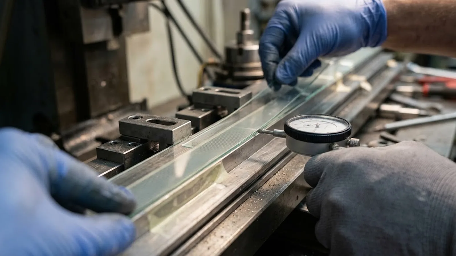
The mounting method's job is to transfer position, not force. Elastic adhesive tape—the default for glass scales up to roughly 2 to 4 meters depending on manufacturer—couples the scale to the substrate through a thin compliant layer that absorbs the differential shear continuously along the length, so the scale follows its substrate without building up tension. Flexible two-part epoxy serves the same purpose where cleanliness or acceleration demands it, but it must be a low-modulus, gap-controlled bond: a rigid bond turns the mismatch back into strain. Both routes require honest surface preparation and the specified bond-line thickness, because the compliance lives in a layer only tenths of a millimeter thick.
Mechanical clip mounting is the alternative for long scales and adhesive-hostile environments. Done correctly, clips hold the scale at defined points and leave the segments between them free; done incorrectly—every hole used, fasteners hard-torqued, no slip allowance—the scale becomes a constrained beam and every kelvin of mismatch turns into bow. Clip spacing follows the manufacturer's tables precisely because those spacings bound the bow amplitude; deviation is a design change, not an assembly liberty. Steel-tape scales invert the logic: they are tensioned so the tape carries the differential structurally, and the correct tension specification replaces the compliance discussion entirely.
Installation temperature completes the method. Substrate and scale should be thermally soaked together at the documented reference temperature before bonding or tensioning, and the machine's mechanical zero established at that same temperature. A pair installed cold and zeroed hot carries a permanent offset frozen into the bond; a pair installed and zeroed at the same documented point gives every later excursion symmetric, calculable behavior around the reference.
Verification is a temperature test, not a temperature assumption. Run the axis through a representative thermal cycle—cold start, warm-up, soak—with an independent length reference (laser interferometer for shorter axes, a step gauge or a thermally decoupled second encoder for longer ones) and log substrate temperature simultaneously. The signature tells the story: linear error tracking temperature and reversing on cooling points at uniform mismatch strain; a sinusoidal component at the clip pitch points at bow; a fast error right after motion starts with slow recovery points at a gradient, usually from the drive motor on the substrate.
Acceptance is a number against the axis error budget: the temperature-correlated contribution of the scale mounting must fit its allocated share, with the design-file calculation confirming the measured slope. A machine that passes owns its thermal behavior explicitly; a machine that never runs the test owns the mismatch invisibly, and it will be rediscovered—slower and more expensively—the first time ambient conditions move outside the commissioning window.
CONCLUSION
CTE mismatch between a scale and its mounting surface is not a second-order refinement of encoder accuracy; on typical machine axes it is the largest single thermal term, it is decided in a materials and mounting drawing, and it is invisible to the encoder's own electronics. The three signatures—position-proportional strain, clip-pitch bow and startup gradient—cover nearly every unexplained thermal drift report on linear axes.
Match the substrate to the surface on paper before ordering, mount with a method that transfers position instead of force, install and zero at a documented temperature, and prove the pair with a logged thermal cycle before qualification. Axes treated this way inherit their thermal behavior as a calculated, bounded quantity; axes that skip the step pay for the same physics later, as debugging time spread across every downstream accuracy claim.
SOLUTION ROUTES
EVIDENCE CHECKLIST
FAQ
Work from the axis error budget rather than a universal number. A practical screening target is a differential contribution below 2–3 micrometers over the largest expected temperature step at full measuring length; a 600 mm scale with 12 ppm/K of differential over a 10 K step produces roughly 72 micrometers, which is why long glass-on-aluminum axes almost always need a different scale material or a compliant mounting method.
It solves the constraint problem, not the expansion problem. Tape lets the scale follow the substrate without tension or bow, but the pair still expands at the substrate's rate—which is exactly what a linear encoder should report. The remaining question is whether the substrate's expansion is acceptable for the machine's dimensional chain.
Not automatically. Low-expansion substrates make the scale nearly thermally static, shifting the temperature sensitivity onto the machine structure and dimensional chain—often right for short nanometer-class axes, but an expensive way to leave the machine's own steel expansion unaddressed on long travels. Near-zero differential where the scale term must vanish; matched expansion where following the machine is correct.
At the documented reference temperature, with substrate and scale soaked together long enough to equalize—typically overnight in the assembly area for cast or granite bases. Bonding at a different temperature than zero-setting freezes an offset into the system; installation and mechanical zero at the same point give excursions a symmetric, calculable behavior.
By the correlation structure. Log axis position error against substrate temperature through a full warm-up and cool-down cycle: linear error tracking temperature with reversal on cooling indicates uniform mismatch strain; a periodic component at the clip spacing indicates bow; a fast error after motion with slow recovery indicates a gradient from a local heat source such as the drive motor.
AUTHORITATIVE SOURCES
TECHNICAL REVIEW
Send the application, critical parameters and any drawing or process information available.
Discuss your application ↗