
First natural frequency separated
Bracket-readhead assembly resonance kept well above the stage's acceleration and disturbance spectrum.
TECHNOLOGY / ENCODER INSTALLATION
The bracket that holds a linear encoder readhead is part of the measurement chain. This guide explains how bracket stiffness, resonance and thermal behavior shape encoder dynamic error and repeatability, and how to design, mount and verify a readhead bracket on a precision stage.
Published
DIRECT ANSWER
A readhead mounting bracket is not a passive accessory; it is a structural element in the position measurement loop. If the bracket flexes under acceleration loads or vibrates at its natural frequency, the readhead moves relative to the scale even when the stage carriage itself has not moved, and the encoder reports that relative motion as position error.
A stiffness-oriented bracket design keeps the first natural frequency of the readhead-to-scale structure well above the stage's dominant excitation frequencies, uses short load paths and symmetric clamping, isolates the bracket from thermally aggressive components, and is verified by dynamic error measurement under real motion profiles rather than by a static gap check alone.
ENGINEERING CONTEXT
Encoder installation guides emphasize gap, alignment and tolerance—all necessary, but all static. What teams discover later, usually during servo tuning or a repeating position ripple investigation, is that the bracket between readhead and carriage introduces its own dynamics. A cantilevered bracket on a fast stage can resonate at a few hundred hertz, adding periodic error that no controller fully cancels; a long overhung arm can bend slightly under every acceleration, so the encoder records a scale error signature that reverses sign with travel direction. These defects are invisible in a static installation check and expensive to diagnose after a machine is in the field.
Discuss your requirement ↗CRITICAL REQUIREMENTS
Bracket-readhead assembly resonance kept well above the stage's acceleration and disturbance spectrum.
Minimal overhang, two-bolt or four-bolt clamping on a machined flat, no cantilevered brackets on high-acceleration axes.
Bracket material and mounting chosen so scale and readhead track the machine structure rather than motor or ambient heat.
Bracket acceptance based on measured dynamic error and ripple under the real velocity and acceleration profile, not only static gap and parallelism.
BUYER MATRIX
Give every shortlisted supplier the same process definition and request configuration-specific proof.
| Design choice | Typical benefit | Typical risk | Best suited for |
|---|---|---|---|
| Machined solid block, short overhang | High stiffness, high first resonance, simple to verify | Heavier; less routing flexibility | High-acceleration linear motors and fast traverse axes |
| Cantilevered bracket | Easy access, compact envelope use | Low lateral stiffness; bends under acceleration; ripple error | Slow, low-load axes only |
| Damped or viscoelastically isolated mount | Attenuates structure-borne vibration into the readhead | Compliance reduces bandwidth of the measurement path | Stage frames with dominant low-frequency vibration |
| Fabricated sheet-metal bracket | Cheap, quick to iterate | Resonance unpredictable; plate modes couple into signal | Prototypes and non-critical axes |
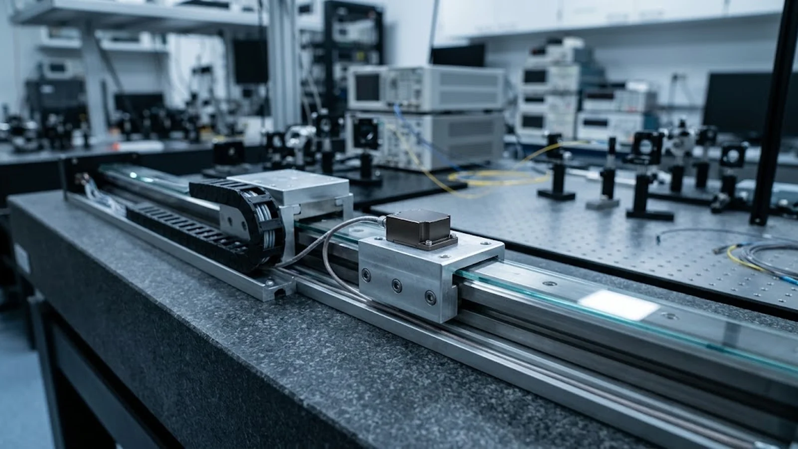
An optical encoder measures relative position between readhead and scale. On a linear stage, the scale is usually bonded to a stable reference surface and the readhead is carried by the moving carriage through a bracket. Every micro-meter the bracket flexes or vibrates appears in the encoder output as motion of the carriage—even if the carriage itself was rigid. In control terms, the bracket sits inside the feedback loop; in metrology terms, it is an unstated transfer function between machine motion and measured position.
This is why two installations of the same encoder model on the same stage can differ measurably. The difference is rarely the encoder; it is the structure carrying it. A bracket with a 300 Hz resonance can turn a clean 50 nm-scale signal into a stage that hums with periodic error, trips diagnostics during high-speed moves, or shows direction-dependent reversal error that no software compensation fully removes.
The governing quantity is not bracket strength but stiffness relative to the excitation spectrum. Each acceleration of the carriage loads the bracket with the readhead mass; each structural vibration of the stage frame enters through the mounting feet. If the first natural frequency of the bracket-readhead assembly sits inside the frequency range where the stage spends its energy—commonly below a few hundred hertz for fast linear-motor stages—the bracket will amplify motion exactly where the servo loop is least able to reject it.
Practical design rules follow from that. Keep the overhang short: the deflection of a bracket arm grows with the cube of its length, so halving the cantilever gains roughly eight times the stiffness. Prefer a machined block or thick plate to bent sheet metal. Clamp with two or more bolts on a machined flat, torque to specification, and ensure the mating surface on the carriage is flat and burr-free—an asymmetric clamp or warped seat introduces a static twist that shows up as yaw error, and a live pivot that shows up as varying gap.
Stiffness is not the only property that reaches the measurement. The bracket conducts heat from the carriage body—often warmed by the motor or by friction—and holds the readhead at a temperature that differs from the scale's. Differential expansion between bracket and scale shifts the readhead gap and, on some scale systems, contributes a small thermal error of its own. On machines with aggressive duty cycles, bracket temperature can be the reason gap and alignment readings taken cold no longer hold after an hour of operation.
Material choice balances stiffness, mass and thermal behavior. Aluminum offers high specific stiffness and fast thermal equalization, and suits most precision stages; steel raises stiffness and damping where envelope allows. What matters most is where the heat comes from and where it goes: shield the bracket from direct motor heating, avoid mounting it to surfaces with large cyclic temperature swings, and verify gap and signal amplitude at both thermal extremes of the real duty cycle.
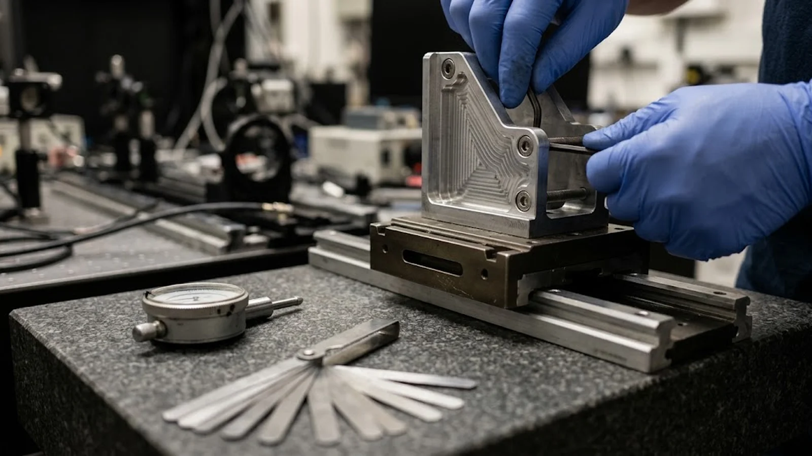
Static acceptance—gap, parallelism, signal amplitude at standstill—is necessary but incomplete. The bracket's character shows under motion. Run the axis through the production velocity and acceleration profile and record dynamic error with the encoder as the reference, or compare against a reference measurement if the machine has one. Periodic error synchronized with a structural frequency points to resonance; an error component that reverses with travel direction points to acceleration-induced bending; a slow shift over the first hour of operation points to thermal behavior.
Simple tests isolate the bracket quickly. A light tap test with an accelerometer on the bracket reveals its natural frequencies. Repeating the same move at different accelerations separates bracket deflection (scales with acceleration) from scale or interpolation error (scales with speed). Tightening or shimming the bracket and watching the error signature change confirms the diagnosis before any redesign. Record these results with the machine documentation so future troubleshooting starts from evidence rather than suspicion.
Treat the bracket as a designed component with its own specification, not a leftover piece of plate stock. The checklist below condenses the practice used on precision stages: define the load case, design for resonance separation, install to tolerance, then qualify dynamically before the machine ships.
When a bracket change is proposed—during retrofit, repair or a performance upgrade—repeat the dynamic verification rather than assuming the new part behaves like the old one. A bracket that measurably reduces dynamic error under the real motion profile is a machine upgrade; the encoder only made it visible.
CONCLUSION
The readhead bracket transfers machine motion into the measurement chain, and everything about it—stiffness, resonance, clamping symmetry and thermal behavior—appears in the encoder signal. Static gap and alignment remain necessary, but they do not certify the installation until the axis has been verified in motion under its real profile.
Specify the bracket with the same rigor as the encoder itself: a defined load case, a resonance target, machined seats and a dynamic acceptance test. Then the position feedback reflects stage motion alone, and the diagnostics that once pointed at 'encoder noise' stay quiet for the right reason.
EVIDENCE CHECKLIST
FAQ
Stiff enough that its first natural frequency sits clearly above the stage's dominant acceleration and disturbance frequencies, and that deflection under the peak readhead acceleration load is small relative to the encoder's accuracy class. The proof is a dynamic error measurement under the real motion profile.
A common cause is bracket compliance: each acceleration bends the bracket, displacing the readhead relative to the scale. The error scales with acceleration rather than speed, and often reverses with travel direction. A stiffer, shorter bracket typically removes it.
Only when the stage frame carries dominant structure-borne vibration that reaches the readhead. Isolation adds compliance to the measurement path, so it is a trade-off to be made from measured vibration data, not a default.
Supplier reference brackets are a starting point sized for typical loads. High-acceleration axes, long overhangs or hot environments justify a custom design and a dynamic verification before release to production.
At commissioning, after any mechanical change, and whenever dynamic error signatures shift. Recording cold and hot gap and alignment readings during routine service keeps thermal behavior visible.
AUTHORITATIVE SOURCES
TECHNICAL REVIEW
Send the application, critical parameters and any drawing or process information available.
Discuss your application ↗