
Stated expansion coefficient
Require the scale coefficient of linear expansion and its tolerance, so the axis error budget and any compensation use the correct value.
TECHNOLOGY / ENCODER SCALE MATERIALS
A linear scale is the dimensional reference of the axis, and its material decides thermal behavior, achievable length, mounting method and long-term stability. This guide compares glass, steel tape and ceramic substrate scales and shows how to match the scale to the machine substrate and travel.
Published
DIRECT ANSWER
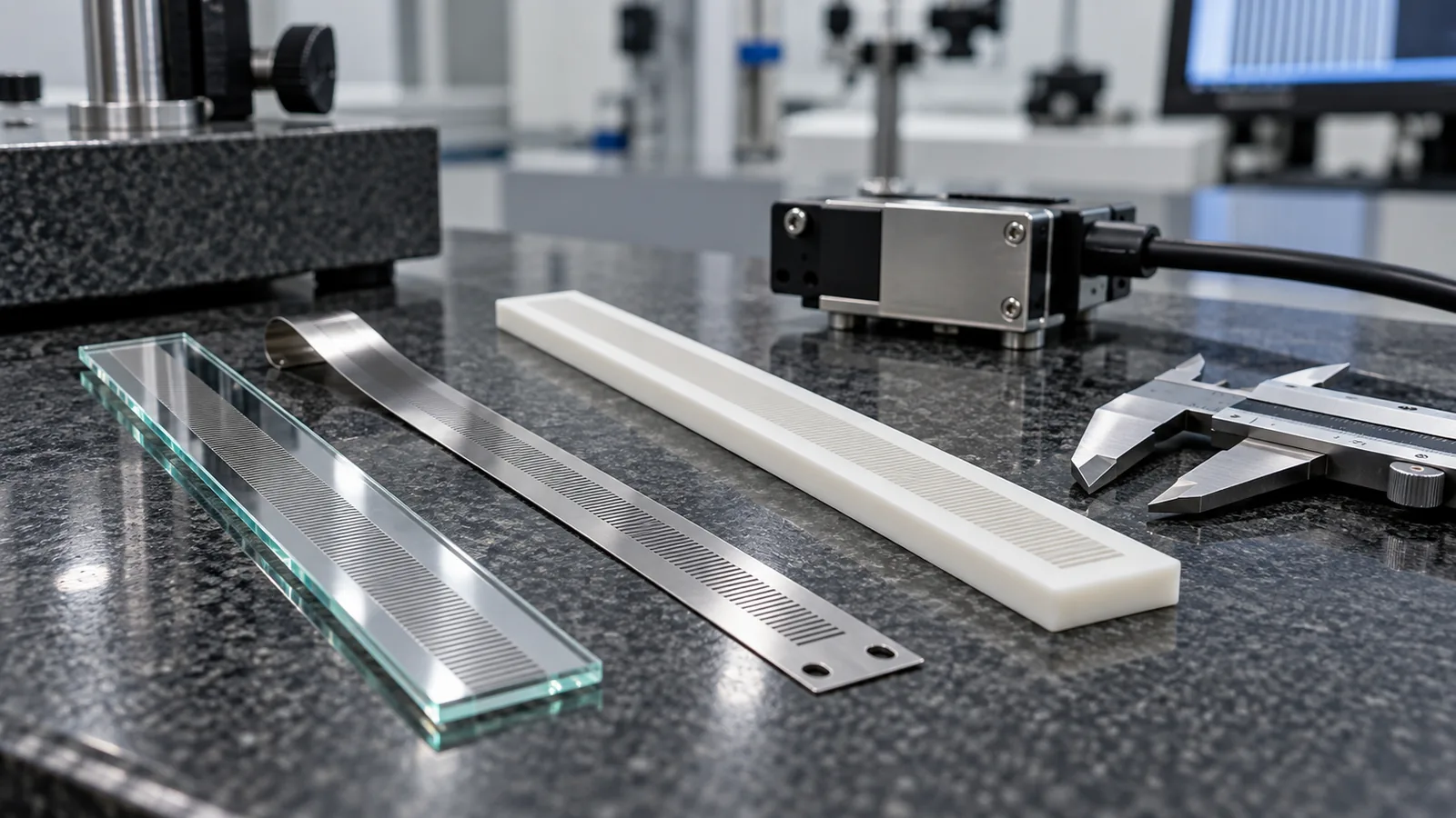
The scale material decides how the encoder reference behaves with temperature, how long a single scale can be, and how it must be fixed to the machine. Glass scales offer fine pitch quality and stable geometry in short-to-medium lengths but are brittle and usually limited to a few metres. Steel tape scales follow the machine substrate and extend to tens of metres, accepting the substrate expansion as their own. Ceramic and glass-ceramic substrate scales provide very low thermal expansion for the highest stability, at the cost of handling care and price.
Selection is a matching exercise, not a ranking. State the machine substrate and its expansion coefficient, the operating temperature range, the required travel and the accuracy target at temperature. Then choose the scale whose expansion behaviour, length capability and fixing method fit that axis, and require the scale coefficient of expansion in writing so any machine-level compensation uses the correct value.
ENGINEERING CONTEXT
Scale material is often treated as a catalogue attribute chosen after the readhead, yet it quietly sets the thermal error budget of the whole axis. A scale with a mismatched expansion coefficient becomes an error generator every time the machine leaves its calibration temperature, and a scale fixed to a substrate it does not agree with is stressed twice: once by the differential expansion, and again by the installer compensating for it. The confusion is deepened by datasheets that quote scale accuracy at a reference temperature without stating the coefficient, and by buyers who assume a longer scale is simply a longer version of the same part. Length limits, fixing methods and handling risks differ so much between glass, steel tape and ceramic that the wrong assumption is usually discovered at installation, when the scale will not sit flat on its base or the axis will not repeat after a temperature change. The fix is to make substrate, temperature range and travel the starting inputs of scale selection, and to require the expansion data that turns those inputs into a defensible choice.
Discuss your requirement ↗CRITICAL REQUIREMENTS
Require the scale coefficient of linear expansion and its tolerance, so the axis error budget and any compensation use the correct value.
Declare the mounting base material and its coefficient, and confirm the scale-substrate pair stays within stress and error limits over the operating temperature range.
Confirm the maximum single-piece length for the chosen material and, for longer travel, the accepted segmentation or tape approach with its joint policy.
Obtain the fixing method, adhesive or clamp specification, substrate flatness requirement and handling limits, including breakage and shipping constraints.
BUYER MATRIX
Give every shortlisted supplier the same process definition and request configuration-specific proof.
| Decision factor | Glass scale | Steel tape scale | Ceramic or glass-ceramic scale |
|---|---|---|---|
| Thermal expansion | Roughly 8 to 10 ppm/K for standard glass; low-expansion variants available | Approximately 10 to 11 ppm/K, close to steel machine structures | Down to near zero for glass-ceramic; extremely stable but must be stated in writing |
| Practical length | Short to medium lengths, typically up to a few metres in one piece | Very long travel, tens of metres, applied as a tensioned strip | Short to medium lengths; long pieces become heavy and fragile |
| Mounting behaviour | Rigid fixing to a flat base; carries its own dimension | Bonded under tension and follows the substrate dimension and form | Rigid fixing with careful stress control; sensitive to local clamping stress |
| Substrate mismatch risk | Moderate on steel; significant on aluminium without compensation | Low on steel structures; on other substrates the tape adopts the substrate expansion | Lowest drift, but joints to dissimilar substrates need stress relief |
| Handling and environment | Brittle; avoid shock, torsion and point loads | Robust in tension; edge damage and corrosion control matter | Brittle and edge-sensitive; cleanroom-style handling advised |
| Typical use | Precision stages, machine tools at controlled temperature, compact axes | Long-bed machines, gantries, linear motor tracks and measuring machines | Metrology frames, ultra-stable stages and thermally compensated structures |
A linear encoder measures position against the scale, so the scale is the dimensional reference of the axis. Its geometry at any moment is the product of its manufactured accuracy and its current thermal state. When the machine warms up, every material in the loop expands at its own rate, and the scale expands with it. If the scale expansion agrees with the dimension the process cares about, drift largely cancels; if it does not, the difference appears directly as position error, often several times larger than the scale accuracy figure printed on the datasheet.
Material choice also decides mechanical reality. Glass must be supported over its full length and cannot follow a curved or stepped base; steel tape must be tensioned and bonded and adopts the substrate form; ceramic substrates hold their dimension superbly but punish shock and point loads. Buyers who select material late, after the mechanics are frozen, lose the freedom to place the scale where these behaviours work. Selection therefore belongs at the concept stage, alongside the substrate and envelope decisions.
Glass is the traditional scale material for precision stages because photolithographic structuring produces very uniform grating with excellent line-edge quality, supporting fine interpolation and low subdivision error. The material is dimensionally self-contained: a rigid glass scale carries its own calibrated length and, when mounted on a flat, stable base, reproduces its factory accuracy in the machine. Standard optical glass expands at roughly eight to ten micrometres per metre per kelvin, and suppliers state the exact coefficient for the batch.
The limits are mechanical rather than optical. Glass will not tolerate torsion, shock or an uneven base, so substrate flatness and fixing quality decide whether installed accuracy matches the certificate. Single-piece lengths are constrained by weight, fragility and straightness control, in practice up to a few metres depending on cross-section. Breakage risk also follows the part through shipping, storage and every service intervention, so packaging and handling instructions deserve the same scrutiny as the optical data. Beyond those lengths, machines move to tape scales or spliced installations, and glass remains the reference for compact, controlled-environment stages where its strengths dominate.
A steel tape scale is a thin graved or etched strip bonded under controlled tension to the machine base. Because it is thin and compliant, it can be produced and shipped in long lengths and applied to beds of many metres, which makes it the default choice for long-bed machine tools, gantries and linear motor tracks. Its expansion coefficient, close to ten to eleven ppm/K, sits near that of steel structures, so scale and substrate drift together and differential error stays small on steel machines.
The same compliance that enables long travel is also the constraint. The tape adopts the dimension and form of whatever it is bonded to, so the substrate becomes part of the measurement reference: its flatness, cleanliness and temperature behaviour all enter the scale error. Installation quality is decisive, since tension errors, adhesive voids and contaminated bond lines show up as local pitch error rather than as an obvious assembly fault. Buyers should treat tape scale installation as a documented process with specified adhesives, rollers, tension values and inspection, not as a fitting task left to general assembly.
Ceramic and glass-ceramic scales exist for one reason: dimensional stability. Glass-ceramic materials can be engineered to expansion coefficients near zero, so the reference barely moves as temperature changes, and the axis error budget is dominated by the machine structure instead of the scale. This makes them the reference of choice for metrology frames, ultra-precision stages and any structure where thermal compensation is deliberately kept simple.
The price is mechanical care and cost. These substrates are brittle, edge-sensitive and heavier than glass at equal length, and clamping them like metal parts introduces local stress that birefringence and micro-cracking convert into slow geometry change. Fixing requires engineered interfaces, compliant layers or defined adhesive patterns, and suppliers state handling and cleaning limits that must reach the installation team. For machines that see shock, shipping vibration or aggressive cleaning, the durability claim should be tested, not assumed.
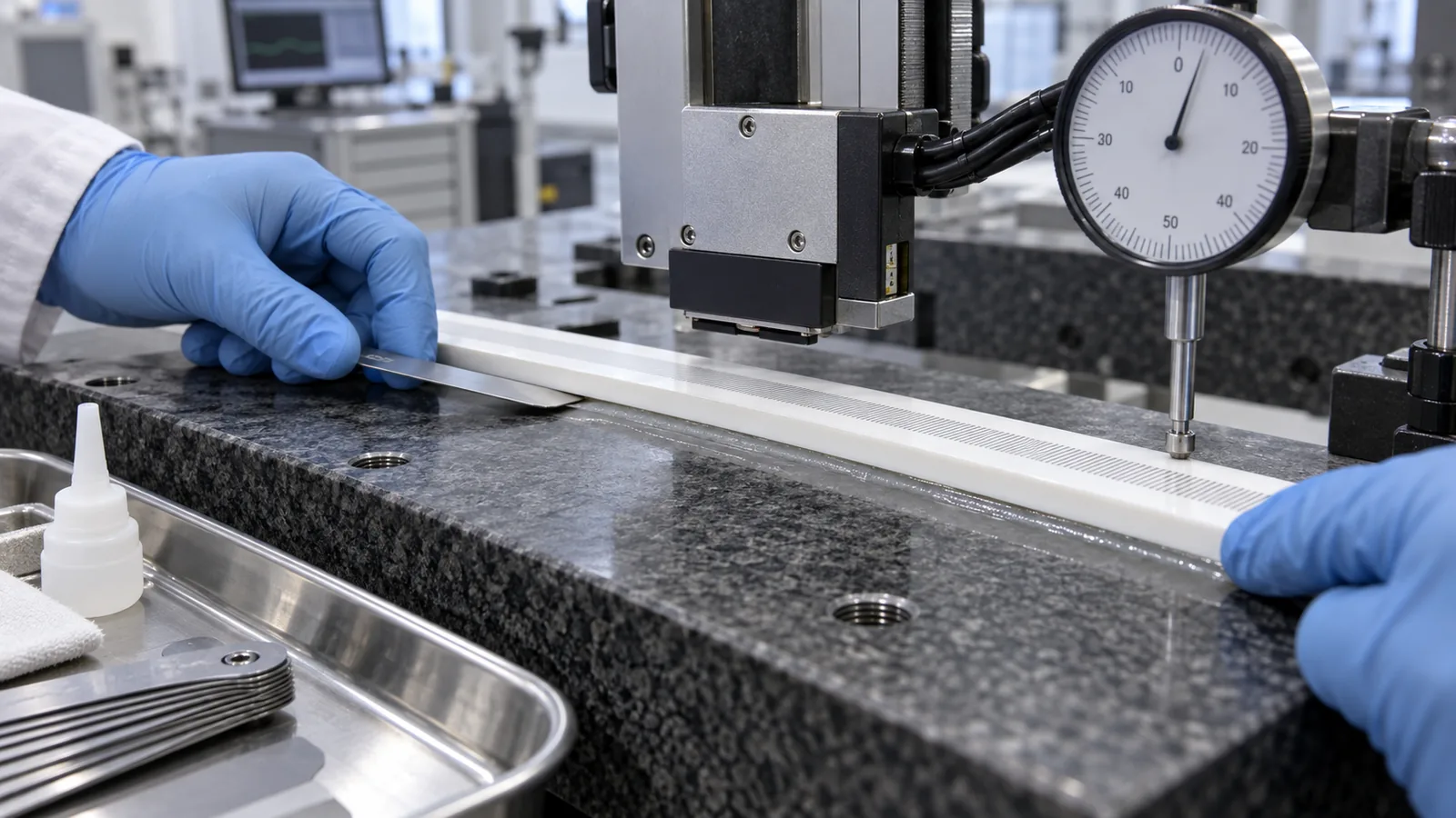
Thermal matching is a budget exercise with three numbers: substrate expansion, scale expansion and the temperature range the machine actually experiences. An aluminium base at roughly twenty-three ppm/K paired with a standard glass scale near nine ppm/K produces a growing differential every kelvin, which must be either accepted in the budget, removed by compensation using the declared coefficients, or avoided by choosing a tape that adopts the substrate. Steel structures pair naturally with steel tape, while granite bases at roughly five ppm/K pair well with low-expansion ceramic scales.
The declared coefficient is only useful if it is the real one. Require the value in writing with its tolerance, confirm whether compensation in the controller assumes scale and substrate coefficients, and record the commissioning temperature. A scale chosen this way keeps its error contribution small and predictable across the working range instead of only at the calibration temperature, which is what the accuracy figure alone would suggest.
Travel decides the construction before preference does. Within a few metres, a single glass or ceramic scale avoids joints entirely and is usually the cleanest solution. Beyond that limit the machine builder chooses between a tape scale, which removes joints but hands the reference dimension to the substrate, and a segmented or spliced installation, which keeps the preferred scale material but introduces joints whose quality must be specified and measured. The choice should be made with the substrate design, not against it.
Whichever route is taken, the installation base carries the final decision. Flatness over the full scale length, support spacing, fixing accessibility and thermal coupling to the structure all determine whether the selected material can deliver its datasheet behaviour. Write the flatness class, fixing pattern and inspection method into the stage drawing, and keep scale replacement possible without reworking the machine. A scale that cannot be serviced is a design error discovered at the first accident.
CONCLUSION
Scale material selection is a matching decision between the scale, the substrate and the temperature range, not a preference for one material. State the expansion coefficients in writing with their tolerances, choose the construction the travel and base can genuinely support, and put fixing, flatness and handling requirements on the drawing. A scale selected and installed this way keeps its error contribution small, predictable and serviceable across the whole working life of the machine.
EVIDENCE CHECKLIST
FAQ
The manufactured scale accuracy is a property of the grating, but the accuracy the machine experiences includes thermal behaviour and mounting. Material sets the expansion coefficient, the practical length and the fixing method, so it decides how much of the datasheet accuracy survives in the installed axis.
It can, but the roughly fourteen ppm/K mismatch between aluminium and standard glass must be handled in the error budget or by compensation using the declared coefficients. On uncompensated axes with wide temperature ranges, a tape scale that follows the substrate is often the more stable choice.
Tape is thin, ships in long lengths and bonds under tension to the machine bed, so tens of metres are practical without joints. The tape adopts the substrate expansion, which is an advantage on steel structures and a reason to control substrate quality everywhere else.
The scale coefficient of linear expansion with its tolerance, the reference temperature behind the accuracy figure, and, for compensated systems, the coefficients assumed by the controller. Without these values the thermal part of the position budget cannot be calculated honestly.
Decide with the substrate. If the base is flat, stable and close to the tape coefficient, tape avoids joints and is usually simpler. If the application needs the grating quality of glass or ceramic over long travel, segmentation with a specified joint process is the route, and the joints must be measured at acceptance.
AUTHORITATIVE SOURCES
TECHNICAL REVIEW
Send the application, critical parameters and any drawing or process information available.
Discuss your application ↗