
Drift measured, not assumed
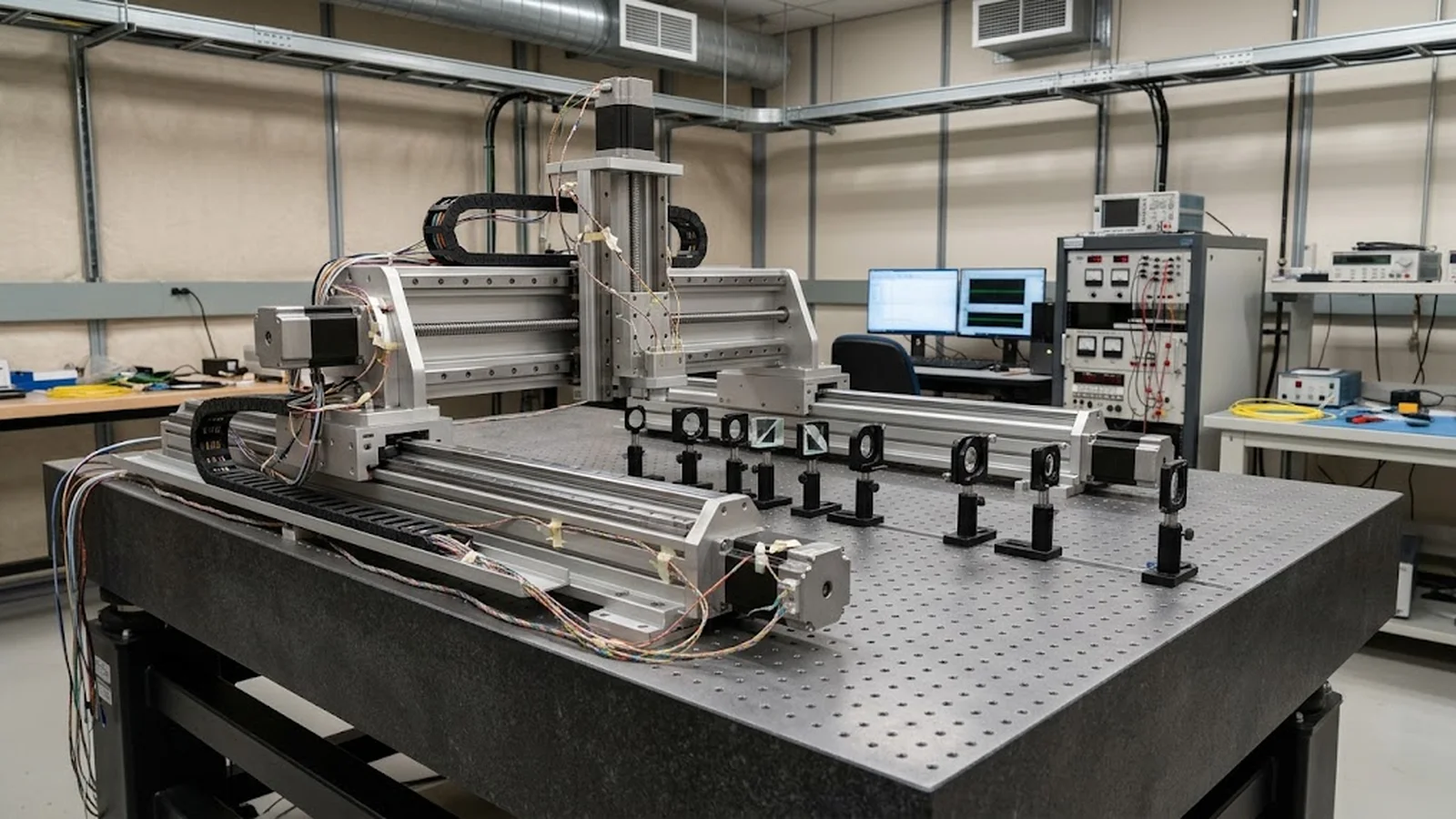
Warm-up curves captured on the actual machine with a reference instrument over the first hours after power-on.
TECHNOLOGY / PRECISION STAGE METROLOGY
Thermal drift is the quietest error source on a precision stage: no alarm, no fault, just position that moves for hours after power-on and shifts again whenever duty cycle changes. This guide explains where stage heat comes from, how warm-up behavior can be measured and shortened, and how to define a stabilization protocol that makes accuracy claims repeatable.
Published
DIRECT ANSWER
Thermal drift on a precision stage is the slow change of position, straightness and scale readings as machine components heat and expand. Drive motors, bearings, friction, cable flexing and even the electronics dissipate watts into structures that expand micrometers per meter per ten degrees. The result is a warm-up curve—position drift over the first hours after power-on—and continued drift whenever velocity, acceleration or duty cycle changes the heat input.
A stabilization protocol controls this by measuring the drift curve on the real machine, defining a warm-up routine that reaches steady state before accuracy work starts, holding the machine's duty cycle inside the qualified envelope, and, where needed, applying thermal error compensation built from temperature sensor readings correlated to measured position error.
ENGINEERING CONTEXT
A stage can pass every static acceptance test at commissioning and still miss its accuracy specification in production. The difference is thermal state. On a cold Monday start, the first hours of work run on an expanding machine: positioning target walks, repeated measurements scatter, and error maps calibrated last week no longer match. Worse, a machine quoted at continuous motion qualifies differently from one doing 20-second cycles with idle gaps, because the heat input pattern differs. Without measured warm-up data and a defined stabilization protocol, thermal drift remains an invisible contributor that every other error source gets blamed for.
Discuss your requirement ↗CRITICAL REQUIREMENTS
Warm-up curves captured on the actual machine with a reference instrument over the first hours after power-on.
A repeatable power-on and exercise sequence that brings the machine to steady state before accuracy-critical work.
Accuracy specifications tied to a stated velocity, acceleration and idle pattern, with drift re-checked when the duty cycle changes.
Temperature sensors and an error model applied only after the drift structure is understood, not as a first resort.
BUYER MATRIX
Give every shortlisted supplier the same process definition and request configuration-specific proof.
| Strategy | How it works | Strengths | Limitations |
|---|---|---|---|
| Defined warm-up routine | Exercise the axes after power-on until measured drift settles | Cheap, effective, no hardware change | Adds minutes to each start; must be followed, not skipped |
| Environmental control | Hold room temperature stable to reduce external gradients | Removes a whole class of drift | Does not address internally generated heat |
| Symmetric thermal design | Motors, cooling and structure arranged so expansions cancel or stay axial | Addresses the cause; benefits every cycle | Design-stage commitment; hard to retrofit |
| Active cooling | Regulate motor or structure temperature to a setpoint | Shortens warm-up; tightens steady state | Cost, noise, and new gradients if poorly placed |
| Thermal error compensation | Model maps sensor readings to position corrections | Recovers accuracy under real conditions | Needs validated model; masks rather than removes heat |
Every energy conversion on a stage ends as heat. Linear motors dissipate copper and iron losses directly into the carriage and stator; guide friction converts motion into heat along the travel; cables flexing in drag chains warm their anchors; drives and amplifiers heat cabinets that share the machine frame. The environment adds its own influence through room temperature swings, solar loads and HVAC cycles. Structures respond on timescales from minutes—small, light parts—to many hours for granite bases and large castings.
The metrological consequence depends on geometry. Expansion along the measurement axis shifts the position reading; expansion across it rotates and curves the guides; differential expansion between scale, structure and metrology frame turns uniform temperature change into shape change. This is why the same watt input can mean micrometers of error on one machine and nanometers on another, and why thermal behavior is a design property, not just an operating condition.
A warm-up measurement is simple in principle: start the machine from a known cold state, run a defined exercise program, and record position behavior with a reference instrument—typically a laser interferometer for displacement drift, plus straightness or angular optics if the guides are of interest. Repeat measurements at fixed intervals capture the curve. What it usually shows is an exponential approach to steady state over one to four hours, with the largest drift in the first half hour and possible direction-dependent behavior as gradients redistribute.
Measure under two heat-input patterns at minimum: continuous motion at production speed, and the real production duty cycle with its idles. They are different machines thermally, and the second one is the one that ships. Record room temperature alongside the drift data; a warm-up curve measured in a 1-degree-stable lab means something different from the same test near a loading door.
With the curve measured, the protocol writes itself from evidence. Define the warm-up routine that brings the critical axes to the flat region: often a staged exercise—slow traverse, then production-speed cycles—for the duration the data showed as settling time, ending with a short verification against a reference or a calibrated artifact. Define what happens after longer stops: a full restart routine after overnight shutdown, a shortened one after a lunch break, depending on how far the machine cools.
Bind the accuracy specification to the protocol. A repeatability or accuracy figure means what it says only in the thermal state where it was measured, so qualification documents should state the warm-up routine, the duty cycle and the room conditions together with the number. When production later changes speed profile or cycle pattern, the drift question reopens—and a quick repeat of the duty-cycle measurement answers it before the schedule does.
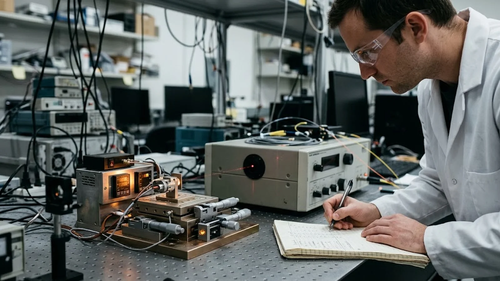
Compensation suits machines whose drift is repeatable and structured: dominant low-order behavior, a few meaningful temperature gradients, and measurement conditions that do not change the structure of the error between runs. The workflow is sensor placement on the heat sources and reference structures, correlation of sensor readings with measured position error across the warm-up and duty-cycle space, a validated model, and periodic revalidation as the machine ages.
Compensation complements—never replaces—thermal design and warm-up discipline. A model trained on a machine with unstable gradients extrapolates badly; sensors on unrepresentative points feed the wrong correction. The strongest practice keeps the chain in order: reduce and stabilize the heat where possible, standardize the thermal state with a warm-up routine, and let compensation trim the residual that remains measurable and repeatable.
Thermal management succeeds as a set of small, enforced habits rather than one large fix. The checklist below reflects what separates machines that hold their accuracy in production from machines that hold it only during qualification: measure the actual behavior, standardize the start, qualify the duty cycle, and re-verify when anything changes.
The payoff is consistency. When thermal state is controlled, repeatability results stop depending on what happened that morning, error maps stay valid between calibrations, and the remaining error sources—mechanical, geometric, dynamic—become visible enough to fix on their own terms.
CONCLUSION
A precision stage delivers its specified accuracy only in the thermal condition where it was measured. Heat from motors, friction and duty cycles moves the machine for hours after start and again whenever the workload changes shape. Measured warm-up curves, a defined start-up routine and a duty-cycle-qualified specification convert that behavior from an unknown into a managed parameter.
Keep the discipline: stabilize first, compensate the validated residual, and re-verify whenever the thermal picture changes. Then accuracy holds through cold starts, long shifts and season changes—and the drift that once hid inside every other error number finally has a name and a protocol.
EVIDENCE CHECKLIST
FAQ
It depends on the machine's mass, heat sources and structure—typically one to four hours to reach steady state, with the largest drift in the first half hour. The correct duration comes from a measured drift curve on the actual machine, not from a general rule.
Continuous operation can still shift as duty cycle changes heat input, as room temperature cycles, or as gradients redistribute between structures. Log position and temperature together to identify which driver dominates.
No. Compensation works best on a machine whose thermal behavior is already stabilized and repeatable. Warm-up discipline and thermal design reduce the error; compensation trims the validated residual.
On the dominant heat sources—motor surfaces, guide blocks, scale mounting structure—and on reference structures that represent the metrology path. Placement should follow the measured drift structure, not convenience.
It can. Different speed and cycle patterns mean different heat input, so drift behavior should be re-measured under the new duty cycle before relying on the original accuracy figure.
AUTHORITATIVE SOURCES
TECHNICAL REVIEW
Send the application, critical parameters and any drawing or process information available.
Discuss your application ↗