
Gap set to mid-window, not to minimum
The installed clearance sits centred in the datasheet window so thermal growth, vibration and contamination each have reserved margin.
TECHNOLOGY / ENCODER MECHANICAL SETUP
The air gap between readhead and scale is the most underestimated encoder installation parameter. This guide explains how gap affects signal quality and contrast, how to set and gauge the clearance correctly, and how to verify the gap holds across travel, temperature and speed.
Published
DIRECT ANSWER
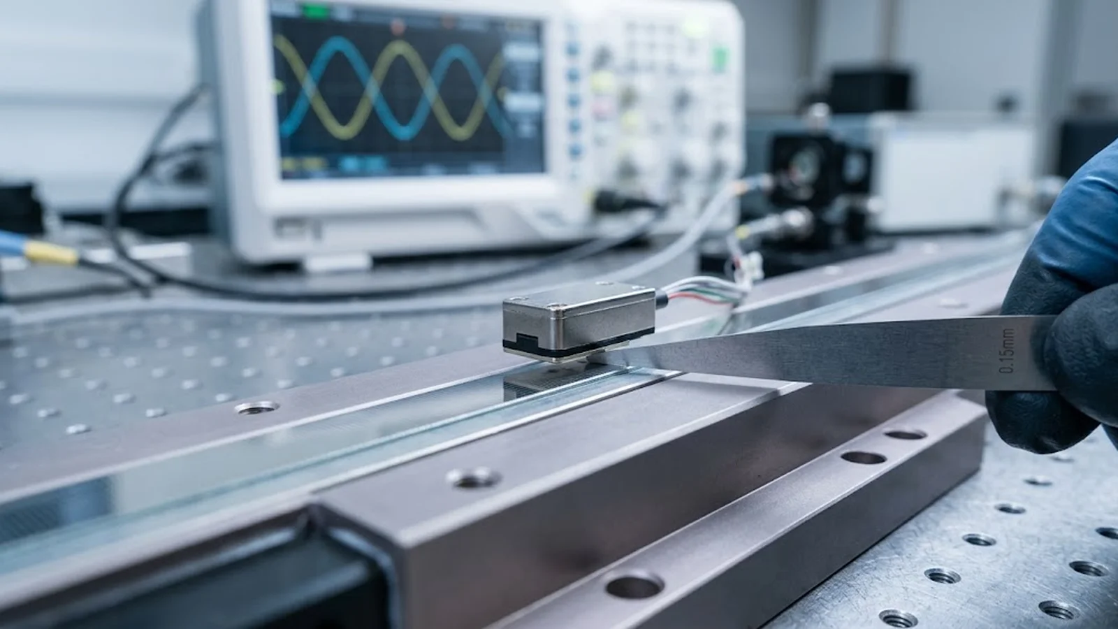
The air gap is the working distance between the readhead's sensing face and the scale surface. Optical encoders derive their position signal from light diffracted or reflected across this gap, so signal amplitude, contrast and tolerance to contamination all depend on the gap staying inside the manufacturer's window. A gap set too small risks contact, debris scoring and thermal collisions; a gap set too large loses optical contrast and drives interpolation error upward before any alarm appears.
Correct setup sets the gap at the middle of the datasheet window after the scale and readhead are mechanically aligned and torqued, using the supplier's gauge or feeler method, at machine operating temperature. It then verifies that the gap—and the signal that reflects it—remains in window across full travel, during warm-up, and at maximum speed, where stage pitch, yaw and vibration transiently modulate the gap. A gap baseline recorded at commissioning turns later signal degradation into a diagnosable trend instead of an intermittent mystery.
ENGINEERING CONTEXT
Encoder installation guides dwell on alignment—parallelism, height, angular tolerances—while the gap is often set 'by eye against the drawing' and never verified again. Yet the gap is the dimension with the least mechanical margin in the whole system: on fine-pitch reflective scales the usable window can be a few tenths of a millimetre, and stage pitch, bracket compliance and thermal growth all act to move the readhead out of it. The failure pattern is characteristic: the axis counts perfectly at slow commissioning moves, then develops amplitude alarms or position ripple at speed, in warm conditions, or months later when contamination has already consumed part of the optical budget. Because the initial gap was never measured or recorded, the first investigation spends days swapping cables and controllers before anyone re-measures a dimension that takes ten minutes with a shim.
Discuss your requirement ↗CRITICAL REQUIREMENTS
The installed clearance sits centred in the datasheet window so thermal growth, vibration and contamination each have reserved margin.
Gap is set with the supplier's gauge, shim or follower method at final torque, not estimated visually against the installation drawing.
Signal amplitude and gap-indicated health are checked at both ends and the middle of travel, cold and after warm-up, and at maximum speed.
The commissioning record states the measured gap, the gauging method, the temperature and the resulting signal levels for later comparison.
BUYER MATRIX
Give every shortlisted supplier the same process definition and request configuration-specific proof.
| Approach | How it works | Strengths | Watch-outs |
|---|---|---|---|
| Visual estimate from drawing | Readhead positioned so the gap 'looks' like the drawing dimension | Fast; no tools | Parallax and bracket flex easily consume the whole tolerance; nothing recorded |
| Set to minimum clearance | Gap placed just inside the lower datasheet limit to 'make sure it sees the scale' | Maximum signal amplitude on day one | No margin for debris, thermal growth or pitch; contact risk on the scale |
| Mid-window with gauge or shim | Supplier gauge or feeler stock sets the gap at final torque, value recorded | Margin both sides; repeatable across technicians | Requires the gauge and a written record; must be done after alignment is final |
| Self-monitoring signal setup | Gap trimmed while watching a diagnostic amplitude or gap indicator | Closes the loop on the actual optical result | Only valid if the indicator is exposed; still needs a physical gap verification |
An optical readhead does not measure the scale by touching it; it projects illumination onto the grating and collects the diffracted or reflected light across the air gap. The phase and intensity relationships that become sine and cosine signals are functions of that distance. Inside the window the readhead was designed for, amplitude and contrast are flat and forgiving. Outside it, they fall away—gradually at first, which is what makes gap errors insidious, because a slightly-too-large gap still produces a signal good enough to count.
The two failure directions are not symmetric. Too small, and the risk is physical: debris trapped between scale and readhead, a dust particle scored across the grating by a moving head, or contact during a thermal excursion or a stage pitch event. Too large, and the risk is electrical: the modulation depth of the received signal falls, the interpolator works closer to its amplitude floor, and sub-divisional error grows while the output still looks healthy on a counter. Neither mode shows up on a slow 'does it move and count' commissioning pass, which is why both keep appearing in the field months after handover.
The gap window itself is not a universal number. It depends on the optical principle—coarse reflective scales tolerate generous gaps, while fine-pitch and diffractive designs use tighter, more sensitive windows—and on the readhead's rated tilt tolerances, because tilt consumes gap margin by varying the effective distance across the sensing field. The only number that matters is the one in the datasheet for the specific readhead and scale combination.
The gap is the last mechanical parameter to be set, not the first. Scale alignment, readhead parallelism and angular tolerances must be finished and fastened to final torque first, because every correction to alignment changes the gap. With the axis stationary at mid-travel, the supplier's gap gauge, shim stock of the specified thickness, or the follower tool supplied with the readhead is inserted between scale and sensing face, the readhead is brought into light contact and clamped, and the gauge is removed. The value is recorded together with the gauging method, the temperature and the axis position.
Target the middle of the window, not the edge closest to a bigger signal. A gap sitting just above the minimum may produce the strongest amplitude on the bench, but it has reserved nothing for the contamination film that will inevitably form, for the bracket creep and thermal expansion that will slowly change the distance, or for the debris particle that must pass through the gap without scoring anything. Mid-window placement converts the datasheet tolerance into real lifetime margin.
Where the readhead exposes a diagnostic amplitude or gap indication, the mechanical gauging and the electrical reading should be closed on each other: set the gap by gauge, confirm the signal level sits where the supplier's documentation says it should for that gap, and note both. A discrepancy between the physical gap and the optical response is itself diagnostic—it points to tilt, contamination on installation, or a scale-reflectivity issue worth resolving before the machine ships.
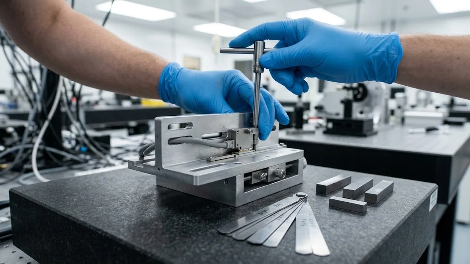
The gap you set is not the gap the machine keeps. Thermal growth changes the distance between the scale mounting surface and the readhead bracket, especially when the two sit on different structures with different expansion coefficients—steel frame against aluminium bracket is the classic combination. Bracket compliance lets acceleration loads deflect the readhead transiently, so the gap modulates with every move; a bracket that is stiff enough on paper can still ring at the axis's motion frequencies. Vibration from adjacent machinery adds a continuous, smaller modulation. Each of these mechanisms alone sits inside the window; together they can push the instantaneous gap out of it.
Verification therefore has to be dynamic. After the static gap is set, the amplitude or diagnostic reading is checked at both ends and the middle of travel, where bracket loading and scale straightness differ. The axis is then run through its warm-up to operating temperature and the readings repeated, separating cold-machine values from production values. Finally a maximum-speed traverse is captured; amplitude dips during motion reveal the gap modulation that a static check cannot see. Any reading outside the window at any state means the mid-window target was not actually achieved in the installed geometry.
A complete installation specification names the datasheet gap window for the exact readhead and scale pair, prescribes the gauging method and the mid-window target, and requires the measured value, temperature and signal levels to be recorded at commissioning. Maintenance documents then reference that baseline: a periodic diagnostic check that compares current amplitude to the recorded gap-related levels catches slow drift early, and any re-set of the gap goes through the same gauging procedure rather than being adjusted 'until the alarm stops'.
For purchasing, the questions that separate a qualified encoder from a catalogue part are: does the supplier state the gap window and tilt tolerance for the specific configuration, does the readhead expose signal level or gap status for monitoring, and can the supplier provide a gauge or fixture for setting the gap? An encoder whose gap cannot be measured, monitored and recorded cannot be commissioned in the engineering sense—it can only be installed. The distinction shows up within the first year of service.
CONCLUSION
Air gap is a few tenths of a millimetre of distance that decides whether the optical budget of an encoder is spent on position measurement or wasted on avoidable loss. Set at mid-window with a gauge, after alignment is final, cross-checked against the diagnostic signal, and verified across travel, temperature and speed, it becomes a stable engineered quantity with recorded margin on both sides.
Record the baseline, re-check it on service intervals, and treat any signal drift by re-measuring the gap first—it takes minutes and it is the parameter most likely to have moved. An encoder whose gap is engineered survives years of thermal cycles, vibration and contamination; one whose gap was set by eye collects intermittent alarms that no one can reproduce at the bench.
EVIDENCE CHECKLIST
FAQ
The working distance between the readhead's sensing face and the scale surface. Signal amplitude, contrast and contamination tolerance all depend on the gap staying within the manufacturer's stated window for the specific readhead and scale combination.
A gap near the minimum maximizes amplitude but leaves no margin for debris, thermal growth or pitch, and raises contact and scoring risk on the scale. Mid-window placement trades a little day-one amplitude for real lifetime margin on both edges.
Last, after scale and readhead alignment are complete and fastened to final torque. Every alignment correction changes the gap, so gauging before final torque produces a value that is obsolete the moment the fasteners are tightened.
By comparing current diagnostic amplitude or gap status against the commissioning baseline, and by re-measuring the physical gap with the gauge during service. Signal checks across full travel, after warm-up and at maximum speed reveal dynamic gap changes a static measurement misses.
Thermal expansion between scale and readhead structures, bracket compliance under acceleration, mechanical creep, and contamination films that effectively change the optical distance. Each is slow and invisible until signal level is monitored against a recorded baseline.
AUTHORITATIVE SOURCES
TECHNICAL REVIEW
Send the application, critical parameters and any drawing or process information available.
Discuss your application ↗