
Installed amplitude inside the window
Signal amplitude measured at the interpolation input, after cable, sits within the datasheet minimum and maximum, not merely above zero.
TECHNOLOGY / ENCODER SIGNAL SETUP
A readhead tuned to nominal signal amplitude on the bench can drift out of window as LED output, contamination and gap change in service. This guide explains gain margin in optical encoder readheads, how to set signal levels with headroom instead of at the limit, and how to verify the margin survives the environment.
Published
DIRECT ANSWER
Gain margin in an encoder readhead is the headroom between the installed signal amplitude and the limits within which the interpolation electronics work correctly. Readheads ship with the gain set for nominal conditions, but on the machine the installed amplitude depends on scale reflectivity, readhead gap, alignment and cable losses, and it changes over life as the illuminator LED ages and contamination builds on the scale. If the gain is set so the signal just reaches nominal at commissioning, any downward drift pushes the amplitude below the minimum the electronics can interpolate cleanly, and the axis starts showing position error or a signal-level alarm.
Correct adjustment sets the installed signal inside the datasheet window with explicit margin on both edges—typically centring the level after the mechanical installation is final, verifying amplitude balance and DC offsets channel by channel, and confirming that automatic gain control, where present, is not already saturated. A documented gain-margin check at commissioning converts signal drift from a mystery failure into a quantity that can be trended and serviced on schedule.
ENGINEERING CONTEXT
Commissioning checklists often reduce encoder setup to 'signal present, count moves'. The gain potentiometer, or the automatic gain loop, is left wherever the readhead happens to land, as long as the drive accepts the signal. Months later, with a few thousand hours on the LED and a film of process residue on the scale, amplitude has dropped well below the interpolation floor: the stage develops position ripple, misses steps at speed or throws an intermittent alarm that never reproduces at the bench. Because no baseline was recorded, nobody can say whether the encoder, the cable or the controller changed. Gain margin is the difference between an encoder that was installed and one that was commissioned.
Discuss your requirement ↗CRITICAL REQUIREMENTS
Signal amplitude measured at the interpolation input, after cable, sits within the datasheet minimum and maximum, not merely above zero.
The commissioning record states headroom to the minimum limit and clearance from the maximum limit, so future drift can be judged against a baseline.
Amplitude ratio between channels and DC offsets are set or checked alongside overall gain, since interpolation quality depends on both.
Where the readhead has automatic gain control, its operating point is recorded; an AGC already at the end of its range has no margin left to give.
BUYER MATRIX
Give every shortlisted supplier the same process definition and request configuration-specific proof.
| Approach | How it works | Strengths | Watch-outs |
|---|---|---|---|
| Factory preset, no check | Readhead used as shipped | Zero effort | Installed amplitude unverified; drift consumes invisible margin |
| Set to nominal at install | Gain trimmed until amplitude matches the datasheet nominal value | Correct level at day one | Centres nothing if gap or scale differ from nominal; margin still unstated |
| Centre in window with margin | Level placed mid-window after mechanical final, both edges measured | Maximum tolerance of LED aging and contamination | Requires a diagnostic output or scope access and a written record |
| Automatic gain control only | AGC loop holds amplitude without manual trim | Compensates slow drift continuously | AGC can saturate; it masks the drift instead of reporting it, and cannot fix balance or offset |
An optical readhead produces sinusoidal signals whose amplitude depends on light reaching the detector: LED output, scale reflectivity, readhead gap and tilt, and the transmission of every optic in between. The interpolation electronics, whether analog phase methods or sampling-based digital ones, only produce accurate position within a stated amplitude window. Gain margin is the distance from the installed operating point to each edge of that window. It is not a property of the readhead alone—it is a property of the readhead as installed on the particular scale, at the particular gap, through the particular cable.
This is why the factory setting is only a starting point. A readhead preset for nominal amplitude on a reference scale can land high or low on the machine. Too little amplitude and the interpolator loses phase accuracy near its floor, producing sub-divisional error growth and eventually lost counts or a level alarm. Too much amplitude and the front end saturates, clipping the sinusoids; the zero crossings survive, but phase relationships between channels distort and interpolation error rises even though the counting looks healthy. Both failure modes pass a casual 'does it count' test.
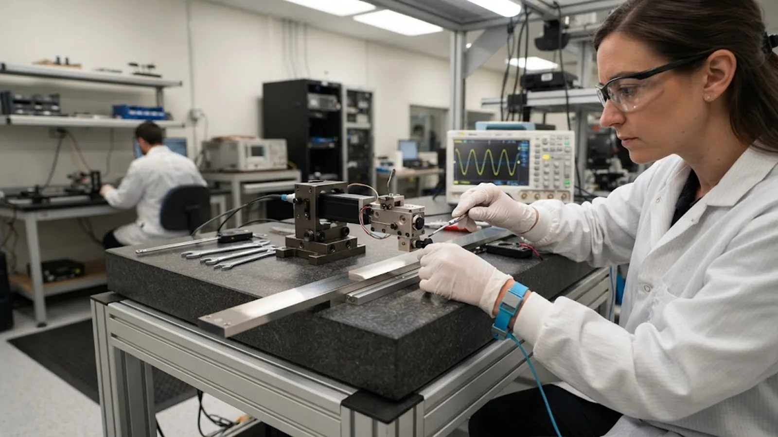
Gain adjustment comes after mechanics, never before. The scale and readhead must be at final alignment and final gap, tightened as installed, because every mechanical parameter feeds the amplitude. With the axis stationary and the diagnostic output or scope connected, each channel's amplitude, DC offset and—the case of quadrature systems—the ratio between channels are measured. Gain is trimmed until the levels sit centred in the window: enough above the minimum that LED aging and contamination can consume their share over years of service, enough below the maximum that temperature-driven swings and gap tolerances cannot clip.
Where the readhead provides automatic gain control, the manual step is different but not optional: verify that the AGC is holding the level from inside its range, not pinned at an end stop, and record its operating point. An AGC with spare range is a genuine margin maintainer; an AGC already at its limit is telling you the optical budget is wrong and the drift has nowhere left to hide.
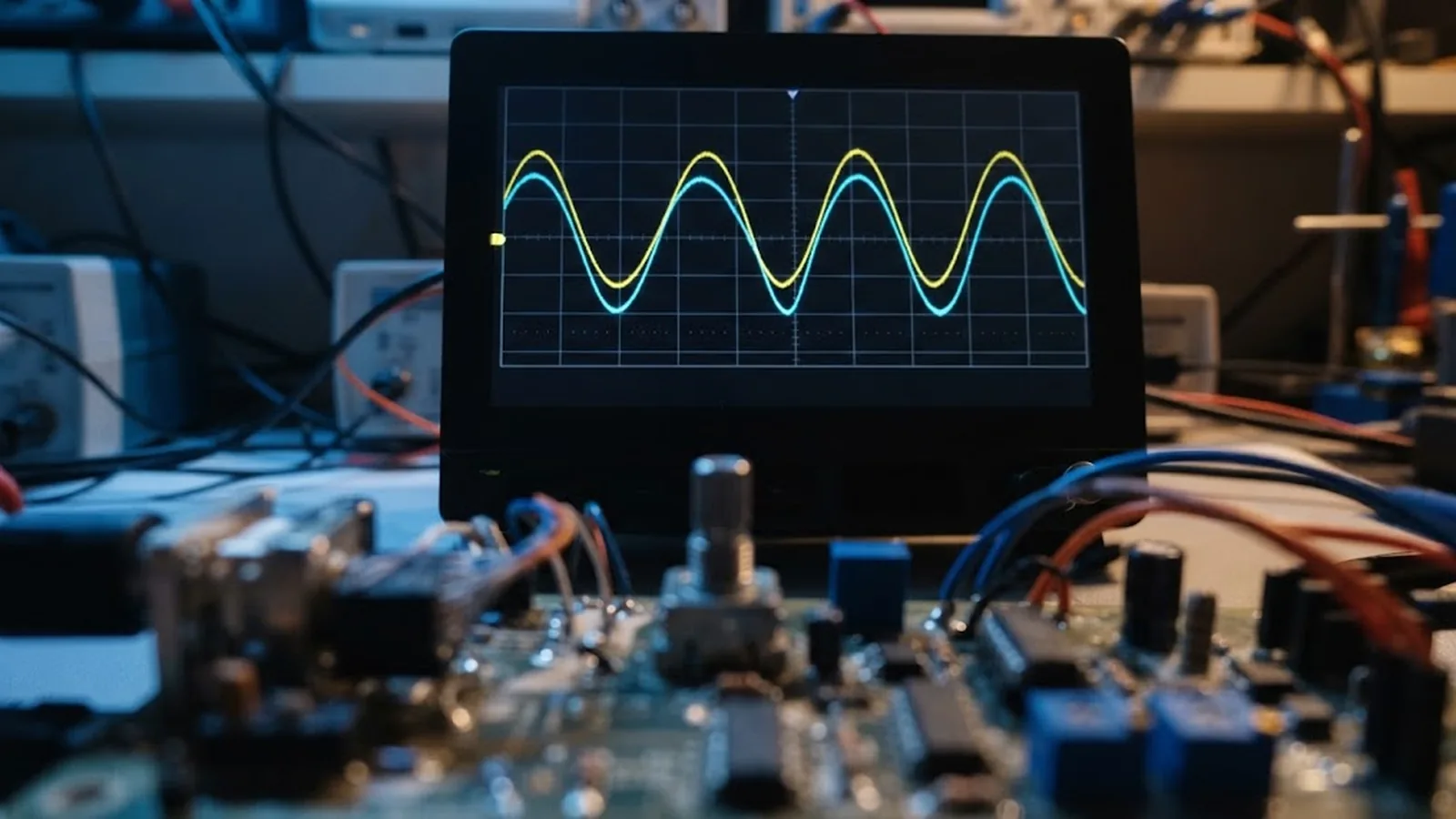
Signal amplitude degrades on predictable trajectories. LED output declines logarithmically with hours and accelerates with temperature, so a hot axis ages its illuminator faster than the datasheet's ambient figure suggests. Contamination—process outgassing, lubricant mist, dust—attenuates light gradually and then abruptly as films reach optical thickness. Mechanical creep shifts gap and alignment by microns. None of these announce themselves; the controller keeps counting until the amplitude finally crosses a threshold, at which point the failure looks sudden while the cause was years in the making.
This is why the commissioning baseline matters more than the trim itself. A level recorded at install turns a later 'signal weak' alarm into a trend: compare the current diagnostic reading to the baseline, and you can distinguish a slow LED decline, which fits scheduled preventive replacement, from a sudden contamination event or a mechanical shift, which calls for inspection. Diagnostics that expose signal level as a readable parameter make this trendable automatically; otherwise a periodic scope check on service intervals does the same job.
A complete commissioning specification requires the installed amplitude window to be stated, the levels measured after installation and recorded with instrument and conditions, and margins to both window edges quantified. For purchase, ask how gain is set—manual trim with diagnostic access, or AGC with a readable operating point—and insist that signal level is exposed for monitoring, because an encoder that hides its own amplitude cannot warn you before it fails.
The payoff is measured in avoided downtime. Axes commissioned with documented gain margin rarely surprise their owners: drift is visible years ahead, servicing is planned, and when something does go wrong, the baseline separates encoder drift from cable damage and controller faults in minutes. An encoder commissioned by 'it counts' delivers the opposite: failures that arrive unannounced and diagnoses that start from zero.
CONCLUSION
Signal amplitude is the vital sign of an optical encoder, and gain margin is the reserve that keeps it alive through LED aging, contamination and mechanical drift. Setting that margin deliberately—after mechanics are final, centred in the datasheet window, per channel, with the AGC state captured—turns a factory preset into an engineered operating point.
Record the baseline, expose the level for monitoring, and re-check on service intervals. With that discipline, amplitude drift becomes a trend you schedule around instead of an alarm you troubleshoot blind.
EVIDENCE CHECKLIST
FAQ
The headroom between the installed signal amplitude and the upper and lower limits of the amplitude window in which the interpolation electronics work to specification. It depends on the complete installed system—scale, gap, alignment, cable—not on the readhead alone.
Nominal is only correct if the installed optics match factory reference conditions. Centring the level in the window after mechanical installation maximizes tolerance of LED aging, contamination and gap variation, which all push amplitude away from its initial value over service life.
No. AGC compensates slow amplitude drift, but it can saturate at the end of its range, it does not correct channel balance or DC offsets, and a pinned AGC reading is itself a warning that the optical budget is exhausted. The operating point should be verified and recorded.
Mainly LED output decline with operating hours and temperature, contamination films on the scale or optics, and slow mechanical changes in gap and alignment. The drift is gradual and invisible unless signal level is monitored against a commissioning baseline.
Per-channel amplitude, balance and DC offset measured at the interpolation input after the cable, the AGC operating point where fitted, the instrument used, the gap setting, and the resulting margins to both window edges—so future readings can be compared against a known starting point.
AUTHORITATIVE SOURCES
TECHNICAL REVIEW
Send the application, critical parameters and any drawing or process information available.
Discuss your application ↗