
Life claim with its conditions
Require LED luminous flux maintenance data at the stated drive current, duty cycle and junction or case temperature used in the readhead, not a generic lifetime statement.
TECHNOLOGY / ENCODER RELIABILITY
An encoder LED rarely fails by going dark; it dims until signal amplitude, interpolation error and jitter quietly leave specification. This guide explains how luminous decay reaches the feedback loop, why MTBF is not a life claim, and what lifetime evidence to require before acceptance.
Published
DIRECT ANSWER
An optical encoder illuminator usually does not fail catastrophically. It dims. Radiant output decays gradually, the sine and cosine signals lose amplitude, and the readhead either raises gain to compensate or quietly accepts a worse signal-to-noise ratio. As the Lissajous radius shrinks relative to fixed offset, phase and quantisation imperfections, interpolation error amplitude and position jitter both grow. The axis keeps working, so the drift is invisible until noise is already limiting the process.
Specify lifetime as a measurable signal condition, not as an LED hour rating. Require the illuminator part number with its drive current and stated junction or case temperature, luminous flux maintenance data for that exact LED, and encoder-level evidence of signal amplitude and subdivision error versus ageing hours at that temperature. Then define the end-of-life criterion as a percentage drop below the signal amplitude recorded at commissioning, at the installed readhead gap and temperature, with margin against the interpolation error budget. Ask whether that source is replaceable, and what a replacement restores.
ENGINEERING CONTEXT
A LED lumen-maintenance figure and an MTBF number look like answers to a lifetime question, and neither is. Lumen maintenance describes luminous output at a stated drive current and temperature; MTBF describes the failure rate of randomly failing items over a defined population and period. Neither tells a machine builder when the encoder stops meeting the interpolation error, jitter and signal-margin limits the axis was purchased to hold. The gap matters because modern readheads hide the transition: automatic gain control keeps the internal signal inside a usable window, diagnostics report healthy until they do not, and a machine that has drifted for two years still passes the short demo used to prove it works. The buyer discovers the problem when yield drops, when the servo starts sounding rough, or when the illuminator is out of production alongside the encoder. The fix is to move the conversation from how long the LED lasts to what signal condition the feedback loop requires, how it will be monitored, and how the illumination will be restored when it reaches that limit.
Discuss your requirement ↗CRITICAL REQUIREMENTS
Require LED luminous flux maintenance data at the stated drive current, duty cycle and junction or case temperature used in the readhead, not a generic lifetime statement.
Define the useful life as the point at which measured signal amplitude, subdivision error or jitter leaves the budget the axis needs, and record the commissioning baseline.
Confirm the readhead reports signal amplitude or an equivalent quality index in a documented format, with a recommended advisory and replacement threshold.
Establish whether the illuminator is a serviceable module or part of a sealed readhead, what a replacement restores, its lead time and availability, and how it will be verified after fitting.
BUYER MATRIX
Give every shortlisted supplier the same process definition and request configuration-specific proof.
| Observed effect | Cause in the illumination path | Effect on the feedback loop | What to specify instead |
|---|---|---|---|
| Gradual luminous decay | LED chip degradation accelerated by junction temperature and drive current | Signal amplitude falls, Lissajous diameter shrinks and offset or phase errors occupy a larger fraction of the period | An action threshold on measured signal amplitude or quality index recorded at commissioning |
| Transmission loss in the optical path | Connector, window, fibre or light-guide ageing, deposits or haze | Amplitude loss that looks like LED decay but worsens faster in contaminated or humid environments | Sealed optical path declaration, cleaning constraints and a contamination life test |
| Thermal output shift | Change in LED radiant output and wavelength with junction temperature | Slow amplitude and contrast drift correlated with warm-up and duty cycle rather than with position | Conduction and air path evidence plus a warm-up and duty-cycle-stated life condition |
| Automatic gain control masking | Gain rising to hold the internal signal inside its usable window | Healthy-looking diagnostics while the noise floor is amplified and true margin is nearly gone | Require raw or uncompensated amplitude reporting and the gain-control range in the specification |
| Random catastrophic failure | Bond wire, interconnect, ESD or moisture-driven defect rather than wear-out | Immediate loss of the axis with no preceding trend | Random failure rate stated with conditions, a field-replaceable module and a defined spare quantity |
| Driver current drift | Ageing or drift in the constant-current source feeding the LED | Slow amplitude change indistinguishable from LED decay without driver-level diagnosis | Require the life claim to cover the complete illumination module, not the LED alone |
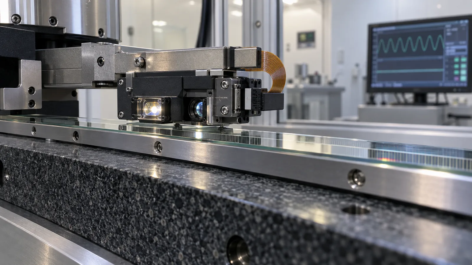
An optical encoder readhead contains a small precision illumination and imaging system. A LED, usually visible or near-infrared, is conditioned by a lens or condenser and delivered to the scale grating; the returning modulated light then falls on photodiodes or a detector array that generate the sine and cosine signals the interpolator divides. Everything downstream assumes those signals arrive with adequate amplitude, good DC symmetry and stable quadrature. The illuminator is therefore the energy reference for the whole measurement, and any change in its output enters the loop before any electronics can compensate.
This makes illuminator ageing behave differently from other wear mechanisms. A worn bearing shows up as lost stiffness; a contaminated scale shows a localised error tied to a travel position. Reduced illumination degrades the underlying signal uniformly, moving several specification terms at once: signal-to-noise ratio, interpolation error, position jitter and eventually counting integrity. A buyer tracking only accuracy may see nothing until most of the margin is gone, so amplitude and quality belong in the maintenance plan rather than only the factory record.
Readhead electronics operate on analogue signals with a finite noise floor. As amplitude falls, residual offsets, phase error and quantisation occupy a growing fraction of the period. Since interpolation divides that period, a shrinking Lissajous radius with unchanged absolute imperfections means each nanometre of distortion represents a larger fraction of the cycle. The first visible consequence is rarely a position error trend; it is increased jitter and velocity ripple at rest and at constant speed.
The second effect is subtler. Automatic gain control, common in modern readheads, holds the internal signal inside a usable window by raising gain as illumination falls. That preserves Lissajous shape and delays visible error, but it also amplifies noise and hides the decay from the operator. A readhead near the top of its gain range can look healthy in a short demonstration while sitting one step from the point where gain saturates and error grows quickly. The number worth writing into acceptance is therefore measured amplitude or a documented quality index, not whether the axis still moves.
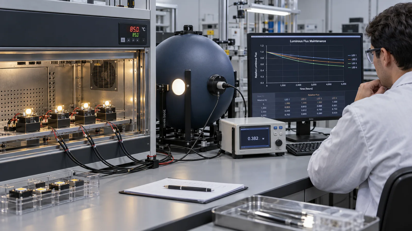
LED life is conventionally expressed as lumen maintenance: the time for output to reach a fraction of its initial value, commonly L70, extrapolated from thousands of hours of accelerated testing at stated currents and temperatures. It answers how much light the component produces, not whether the encoder still meets its error budget. MTBF is a statistic describing random failures across a population over a defined period, usually under conditions no machine reproduces. Neither tells a designer when subdivision error moves outside tolerance.
Reading either requires its conditions. Ask whether the readhead drive current matches the test condition, at what junction temperature the projection was made, whether the tested duty cycle matches continuous machine duty, and whether the value covers only the LED or the complete illumination module including optics, fibre and driver electronics. Test duration matters too: a projection reaching far beyond the measured interval carries less credibility than one anchored to long data. Treat both numbers as inputs to a translation exercise, not as the answer.
The practical criterion is a signal condition tied to the interpolation error budget. Record signal amplitude, or whatever quality metric the readhead supports, at commissioning, together with the gap, temperature and duty cycle at which it was taken. Then define two levels: an advisory level triggering investigation, typically a modest percentage drop from baseline, and a replacement level set with margin against the amplitude at which subdivision error leaves its budget. Because the criterion is measured in the installed state, it covers LED degradation, optical contamination and driver drift at once.
Wear-out is not the only failure mode. LEDs and their interconnects also fail catastrophically through bond wire fatigue, electrostatic damage or moisture ingress, producing no trend at all. A useful lifecycle plan therefore combines the trended signal criterion with a spare policy sized to the installed base, a documented replacement procedure and a verification step after fitting. Machines that cannot tolerate unplanned stops should schedule illumination restoration during planned downtime rather than wait for the advisory threshold.
Architecture decides how much is recoverable in the field. An illuminator built as a serviceable module separates the LED, its optics and sometimes its driver from the readhead body, so illumination can be restored without disturbing readhead alignment or replacing the electronic assembly. The penalty is an extra optical interface, a connector, another dust and moisture path and one more item whose availability must be managed. In a clean, dry machine enclosure that trade is usually attractive.
A sealed integrated design keeps the optical path closed, which supports the contamination, humidity and sealing story and removes electrical interfaces that can drift or pick up noise, but illumination loss then means replacing the readhead, confirming the gap and repeating the acceptance check. Neither architecture is universally better. Ask whether replacement restores the original amplitude and subdivision error, whether it can be done in place, what verification follows, what the lead time is, and how availability is guaranteed over the machine service life.
Ask for four documents and one number. The documents are the illuminator part identification with drive current and duty cycle, luminous flux maintenance data for that exact LED at stated current and temperature, encoder-level amplitude and subdivision error versus ageing hours at the operating temperature, and the diagnostic specification describing how amplitude or a quality index is read from the installed encoder. The number is the end-of-life threshold recommended for that configuration, justified against the interpolation error budget.
Then turn it into a maintenance record. At acceptance, record the baseline amplitude with gap, temperature and interface conditions noted, load the advisory and replacement thresholds into the maintenance plan, and repeat the measurement at intervals using the same method. If the supplier cannot provide accelerated data for the LED or encoder-level evidence of drift, the honest position is that installed lifetime is unknown, and the sensible mitigation is a spare policy and a scheduled replacement rather than confidence in an hour rating.
CONCLUSION
Illuminator ageing is a performance budget problem wearing the costume of a reliability problem. Define useful life in the currency the feedback loop understands: measured signal amplitude and subdivision error at a stated gap, temperature and duty cycle, recorded as a baseline at commissioning. Choose between a serviceable illuminator and a sealed readhead from the machine service strategy, and write the monitoring method and availability terms into the purchase specification.
SOLUTION ROUTES
EVIDENCE CHECKLIST
FAQ
No. MTBF describes the random failure rate of a population over a defined period under stated conditions. It does not describe the gradual luminous decay that limits most LED-based illuminators, and it does not tell you when interpolation error leaves its budget.
A sustained drop in measured signal amplitude, or in the quality index the readhead reports, relative to the commissioning baseline taken at the same gap and temperature. Set an advisory level for investigation and a replacement level with margin against the amplitude at which subdivision error leaves budget.
Yes. Gain control holds the internal signal inside a usable window, so the readhead can report healthy while noise is amplified and true margin is nearly exhausted. Request raw or uncompensated amplitude reporting and the gain range as part of the specification.
It depends on the machine and its environment. A module allows illumination to be restored in place and cheaply, at the cost of an extra optical interface and aperture path; a sealed readhead improves sealing and removes that interface but ties the illuminator to the electronic assembly for life.
Treat the installed lifetime as unknown and mitigate with a spare policy sized to the installed base, a recorded baseline for trend measurement, and a scheduled replacement during planned downtime rather than reliance on a quoted hour rating.
AUTHORITATIVE SOURCES
TECHNICAL REVIEW
Send the application, critical parameters and any drawing or process information available.
Discuss your application ↗