Encoder Position Compare Outputs: Specifying Hardware Triggers for Precision Stages
A position compare output turns an optical encoder from a measuring device into a timing device: the interpolation electronics watch the measured position and toggle a hardware output when the stage crosses a setpoint, with latency and jitter no software loop can match. This guide explains how position compare and event outputs work, where they earn their place in inspection and laser processing machines, which specifications decide whether an encoder can deliver them, and how to verify trigger quality during commissioning.
Published
DIRECT ANSWER
What should a buyer prioritize?
A position compare output is a hardware comparator inside the encoder's interpolation electronics that continuously compares the measured position against one or more programmed setpoints and switches a dedicated output the instant the stage crosses them. Because the comparison runs in silicon at the encoder's counting rate rather than in a software control loop, the output appears with a fixed latency—typically well under a microsecond—and with timing jitter in the nanosecond range. The result is a trigger signal whose timing uncertainty is set by the encoder's position resolution and the comparator's electronics, not by the load on a controller.
Buyers should specify position compare as a feature of the feedback system, not improvise it in software. The questions that decide usability are concrete: how many comparators are available and how they are set, what latency and jitter the datasheet guarantees, what the output electrically is and how it is re-armed, whether triggers can be placed arbitrarily close together, and how position capture (recording the exact encoder reading at the trigger instant) complements the output. Verified with an oscilloscope during commissioning, these properties determine whether on-the-fly inspection, laser processing, or sensor synchronization delivers usable data at production speed.
ENGINEERING CONTEXT
The decision starts with the real constraint.
Machines that inspect, pattern, or record while the stage is moving eventually hit a timing wall that position accuracy alone does not explain. A camera acquires frames at commanded stage positions, but the images blur because the actual trigger arrived late and by a varying amount; a laser marks a feature at the wrong scale position because the firing command waited for the next control cycle; a data acquisition system sampling on software timers collects unevenly spaced records that corrupt frequency analysis. The root cause is almost always the same: the trigger decision was made in software, on a clock the operating system or the motion loop controls. Software comparisons run at the servo rate—milliseconds between updates, with scheduling jitter layered on top—and even real-time controllers add interface latency between encoder, processor, and output port. Moving the comparison into the encoder electronics removes the entire chain: the comparator sees position at the counting rate and drives a physical output directly, so the machine gets trigger timing that is deterministic by construction. The difficulty for buyers is that datasheets describe this capability unevenly—some encoders list comparator counts and latency figures, some mention only that an 'event output' exists, and some offer position capture without a compare output at all—so the feature must be specified deliberately during selection rather than discovered after installation.
Establish how many independent setpoints the interpolation electronics support, how setpoints are programmed (register writes, cyclic interface commands, or an absolute protocol), how quickly they can be changed in operation, and whether direction and hysteresis around each setpoint are configurable.
02
Latency and jitter stated with test conditions
Require the datasheet to state trigger latency and jitter figures and the conditions under which they were measured, including counting rate and output load. A latency number without conditions is a marketing figure; latency with a spread is a usable specification.
03
Output electrical and re-arm behavior defined
Specify the output electrical type (differential RS-422 pair, TTL, or open collector), its pulse width behavior across stage speed, whether it re-triggers automatically on each crossing, and how far apart two triggers can be placed before the electronics impose a minimum spacing or dead band.
04
Receiver integration planned
Match the trigger to the receiving device—camera expose input, laser fire gate, or acquisition clock—including level conversion, cable type, and whether the receiver needs a latched encoder position delivered over the same event so data can be tagged with the true crossing position.
BUYER MATRIX
Compare evidence, not feature labels.
Give every shortlisted supplier the same process definition and request configuration-specific proof.
Ways to generate position-triggered events on a precision stage
Aspect
Encoder onboard comparator
External counter/compare module
Controller software compare
Protocol position latch (BiSS-C/EnDat)
Trigger decision location
Inside the interpolation electronics, evaluated at the encoder counting rate
In a dedicated counting card watching the encoder signals
In the motion controller or host software at the servo or loop rate
In the encoder or interface electronics, triggered by a protocol command
Typical latency and jitter
Sub-microsecond latency with nanosecond-range jitter; deterministic by construction
Low latency, but depends on the module's clock and bus; jitter usually well below software
Milliseconds between decisions plus operating-system and scheduling jitter
Low jitter for the latched position value; the physical event output depends on the same electronics as onboard compare
Setpoint flexibility
Limited by comparator count and register update speed; changing setpoints on the fly depends on the interface
High: many comparators and frequent updates possible over the card's bus
Unlimited in principle, since any axis position can be tested in code
Setpoints requested over the protocol cycle; suited to repeating patterns and synchronized captures
Best use
On-the-fly inspection, laser firing, and sensor triggering at production speed
Multi-axis trigger logic, legacy retrofits, and systems without encoder-side compare
Slow processes and debugging, where trigger timing tolerances are loose
Absolute encoders feeding drives that need a position value tagged to each event
Main caveat
Availability varies by encoder family; must be ordered and configured deliberately
Adds hardware, cabling, and another latency source to characterize
Cannot deliver deterministic timing no matter how fast the processor
Requires a protocol-capable master and firmware; not a retrofit onto SSI or quadrature-only systems
What a position compare output actually does
An optical encoder's primary job is measurement: the interpolation electronics convert photodetector signals into position counts and deliver them to the drive or controller. A position compare output adds a second, parallel function inside the same electronics. The user programs one or more position setpoints into the interpolation electronics, and a hardware comparator watches the live position at the full counting rate, switching a dedicated physical output within a fixed, short delay the instant the stage position crosses a setpoint. Nothing in this path involves software, an operating system, or a communication cycle—the decision and the output switching happen in the same electronics that count the scale periods.
The consequence is a quality of timing that no other architecture in the machine can offer. Latency—the delay between the true crossing and the output edge—is fixed and small, commonly well under a microsecond, and jitter—the cycle-to-cycle variation of that delay—is in the nanosecond range, set by clock phase and comparator electronics rather than by anything happening in the controller. Because the comparator runs at the counting rate, its timing precision also degrades gracefully with speed: at higher stage velocity the position changes more per clock tick, so spatial trigger placement inherits the quantization of the counting rate, which is exactly the relationship the high-speed counting limits of the encoder describe.
Why software triggers fail the same machines
The obvious alternative—watching position in the motion controller and asserting an output when the setpoint is passed—looks equivalent on a datasheet and behaves nothing like it on the machine. A software comparison happens when the control loop happens to run: at a servo rate of a few kilohertz, the position is sampled milliseconds apart, and the trigger edge lands somewhere inside that interval. Operating systems add scheduling nondeterminism on top, and even hard real-time controllers insert interface latency between the encoder input, the processor, and the output pin. The result is trigger timing whose error is measured in fractions of a millisecond and varies shot to shot.
At a stage speed of 200 mm/s, one millisecond of timing uncertainty is 200 micrometers of position uncertainty—larger than the feature size most precision machines exist to produce, and three to four orders of magnitude worse than the encoder's own measurement uncertainty. This is why image blur, misplaced laser features, and unevenly spaced measurement records appear precisely in machines whose feedback was selected purely on resolution and accuracy figures. The trigger is a real-time requirement with its own specification, and it belongs in hardware at the encoder, where the position signal is born.
Where hardware triggers earn their place
On-the-fly inspection is the canonical application. A camera on a precision stage acquires frames while moving, and each exposure must begin when the stage passes a known position; a hardware compare output drives the camera's expose input directly, so image spacing is set by comparator precision rather than by loop timing. The same pattern applies to laser marking, micromachining, and direct-write lithography, where the pulse train that fires the source must be locked to stage position to keep fluence and feature placement uniform across the field.
Metrology and sensor integration form the second family of uses: strobing a profilometer or an interferometer at evenly spaced positions, gating a data acquisition channel so samples land at known coordinates, and synchronizing two axes so a sensor on one stage samples when a feature on the other crosses its field of view. In all of these, the value delivered is the same—events tied to true mechanical position with timing uncertainty the machine's process window can absorb. When the receiving instrument needs more than the pulse itself, most encoder-side implementations can also deliver a latched position value over the communication interface at the trigger instant, so each record is tagged with the exact crossing position rather than the position sampled after the fact.
Specifying compare capability during procurement
Position compare capability is a configurable feature, and it must appear in the order code, not be assumed. The specification to put in front of a supplier is short but specific. First, comparator count and setpoint handling: how many setpoints exist, how they are written (static registers, cyclic updates over the interface, or protocol commands), and whether setpoints can be changed while the stage is moving. Second, guaranteed latency and jitter with test conditions, at the counting rate the machine will actually run. Third, the output itself: electrical interface, drive capability, pulse width behavior across speed, and re-arm behavior—whether every crossing produces a pulse, or whether the electronics must be re-armed between events.
Two practical constraints deserve explicit attention because they appear late and cost dearly. Minimum trigger spacing: comparator electronics need a finite number of counting-clock ticks to re-arm, so triggers closer together than a stated interval are dropped or merged; the machine's finest feature spacing at top speed must sit inside this limit with margin. Direction behavior and dead bands: some implementations suppress triggers in one direction or near count rollovers and reference-mark regions, and a machine that inspects in both directions needs this stated, not discovered. Where the encoder speaks an absolute protocol, the natural home for event data is the protocol itself—BiSS-C and EnDat both define mechanisms for latching position against events—and the interface decision and the trigger decision should be made together, as the BiSS-C and EnDat interface guide explains in detail.
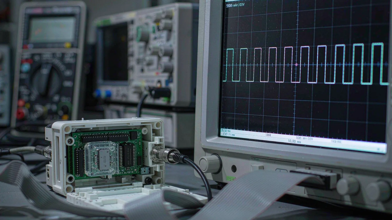
Trigger performance is verified with an oscilloscope and a plan, in the same commissioning session that checks counting integrity. The measurements are concrete. Measure latency by comparing the trigger edge against the encoder's own incremental signals at a known position. Measure jitter by accumulating trigger edges on the scope and reading the spread, then confirming it matches the datasheet within the test conditions. Sweep stage velocity across the process range and record trigger spacing error at each speed, because setpoint quantization grows with velocity and the process window must hold at maximum speed, not on the bench.
Finally, verify the machine-level loop: trigger the actual camera, laser, or acquisition system over the actual cable, and confirm the receiving device's input threshold and timing requirement are met at the end of that cable—differential trigger pairs over twisted-pair cabling behave much like encoder signal pairs, and the same routing discipline applies. A trigger that is electrically clean but arrives outside the receiver's exposure window fails exactly as completely as a jittery one, so the verification ends at the receiving device's data, not at the encoder connector. Machines commissioned this way produce inspection and processing data whose position tags can be trusted at production speed.
Treat the trigger as a feedback-system specification, not a software afterthought.
A position compare output converts the encoder from the machine's measuring instrument into its timing reference, and the machines that need it—on-the-fly inspection, laser processing, synchronized metrology—cannot get equivalent performance from any software alternative. The comparator runs where the position signal is born, so its latency is fixed, its jitter is nanoseconds, and its spatial accuracy follows directly from the counting rate and scale quality the machine already paid for.
The buying discipline is compact: require the compare feature in the order code with comparator count, latency, jitter, and output behavior stated under real conditions; check minimum trigger spacing and direction behavior against the process at maximum speed; and verify the whole chain—comparator, cable, receiving device—on the scope and at the data level during commissioning. Specified and verified this way, hardware triggers stop being a source of unexplained blur and drift and become one of the most predictable subsystems in the machine.
Encoder datasheet section naming the position compare or event output feature, with comparator count, setpoint resolution, and programming method
Latency and jitter figures with stated measurement conditions, ideally an oscilloscope capture at the machine's actual counting rate
Output electrical specification: interface type, level, maximum frequency, pulse width versus speed, and drive capability
Setpoint constraints in writing: minimum trigger spacing, behavior at scale reference marks and count rollovers, and hysteresis around each setpoint
Commissioning record showing measured trigger timing against an independent reference, including spacing accuracy at maximum stage velocity
FAQ
Questions engineers ask before selection.
What is the difference between a position compare output and a regular encoder index pulse?
An index (Z) pulse fires once per scale period at a fixed, manufacturer-defined location, often used only for homing. A position compare output fires at user-programmed setpoints anywhere in travel, at as many positions as the comparator count and re-arm logic allow. The index tells the machine where zero is; the compare output tells the machine when it has reached wherever the process needs an event.
How accurate is the trigger position compared to the encoder's accuracy?
The spatial accuracy of a hardware trigger is the combination of the encoder's measurement accuracy at the crossing point and the timing quantization converted to distance: counting-clock period multiplied by stage velocity, plus the comparator's fixed latency offset. At moderate speeds this added term is typically nanometers to a few hundred nanometers, so trigger placement is usually limited by the encoder's accuracy, not by the comparator.
Can setpoints be changed while the stage is moving?
It depends on the implementation. Setpoints held in registers and updated over the interface can usually be changed on the fly, limited by the interface update rate; compare functions driven by protocol commands (for example over BiSS-C) update at the protocol cycle rate. Any claim of on-the-fly setpoint changes should be verified at the machine's actual speed, checking that no trigger is dropped during the update.
Why not simply use a fast controller or FPGA-based software trigger?
A controller or FPGA can approach encoder-side performance, but it reintroduces the latency chain the encoder comparator avoids: signal transmission to the device, processing, and output driving, each adding fixed delay and its own jitter sources. It also consumes the engineering effort to build and validate that path. An encoder with native compare capability delivers the same result with a datasheet specification and a scope check.
What is position capture, and how does it relate to the compare output?
Position capture records the exact encoder reading at the instant an external or internal event occurs, while a compare output generates an event at a programmed position. They are complementary: the output tells the rest of the machine when to act, and the captured position tags each action with the true crossing coordinate. Many absolute interfaces combine both, latching the position value into the protocol data stream at the trigger instant.