Straightness Error Measurement on Precision Linear Stages: ISO 230-1 Methods, Data Evaluation, and Reversal Techniques
Straightness error of a linear stage limits how accurately a moving component follows a straight line, and it propagates directly into stacked-axis positioning and squareness. This guide explains the ISO 230-1 definition, the three practical measurement methods—straightedge with dial indicator, autocollimator, and laser interferometer straightness optics—plus data evaluation, reversal techniques, and how straightness relates to squareness, parallelism, and volumetric error.
Published
DIRECT ANSWER
What should a buyer prioritize?
Straightness error, as defined in ISO 230-1, is the minimum-width zone between two parallel lines that contains the actual trajectory of a moving component along a specified axis, evaluated in a defined plane. For a precision linear stage it is measured twice per axis: horizontal straightness, the deviation of the carriage path in the horizontal plane containing the axis, and vertical straightness, the deviation in the vertical plane. Together with angular error motions, these translational deviations determine how far a tool point or end-effector actually wanders from the ideal line while the position readout reports perfect travel.
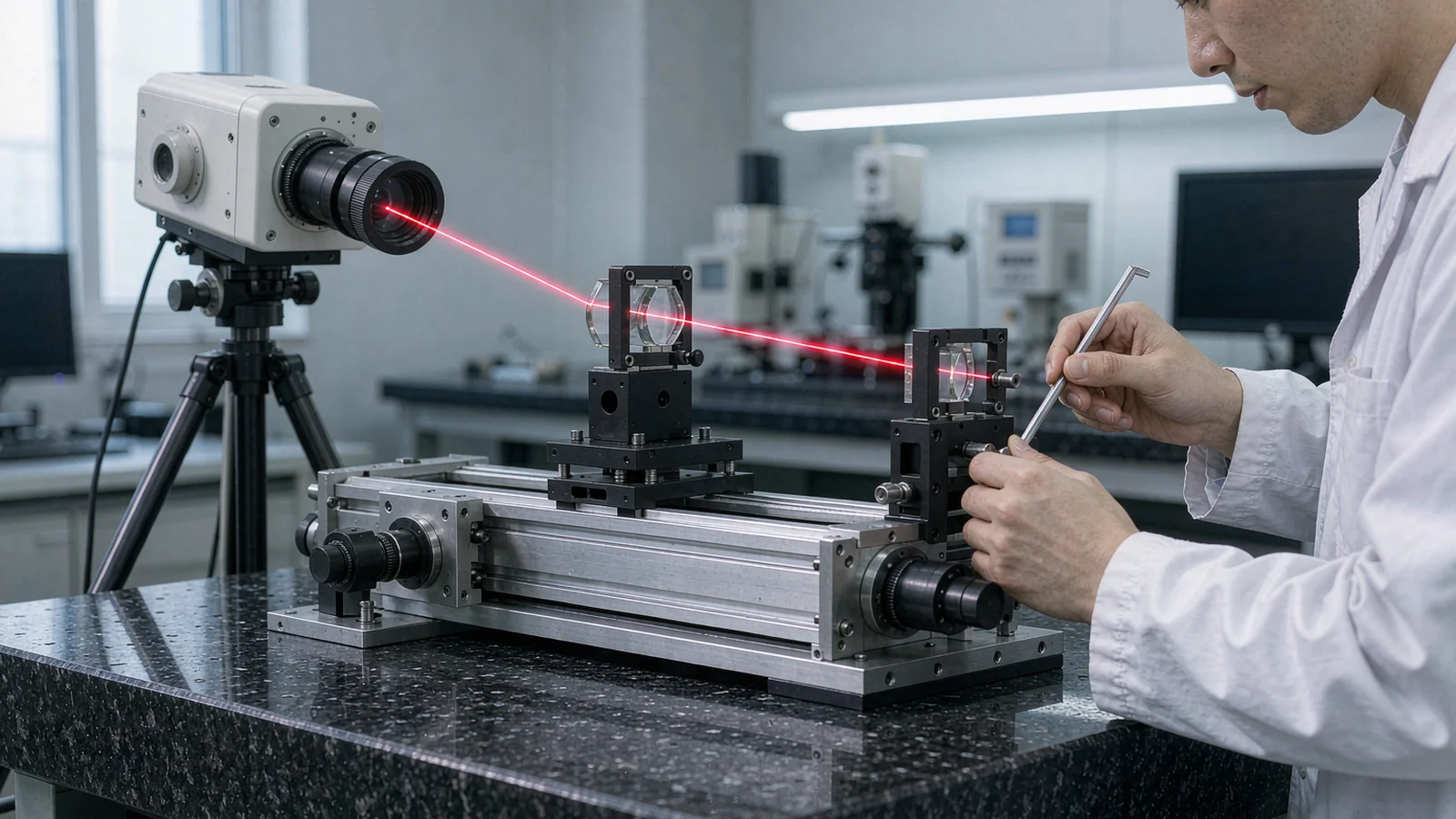
Three measurement methods cover essentially all practical cases. A straightedge and dial indicator is the simplest shop-floor method, limited mainly by the quality of the reference straightedge. An autocollimator measures angular tilt of a mirror carriage step by step along the axis, from which straightness is obtained by integration; it offers excellent resolution over long travels but needs careful setup. A laser interferometer with straightness optics—a Wollaston prism and a straightness reflector—measures lateral displacement directly against a straight reference beam and is the standard choice for precision stages, typically combined with a reversal technique to separate the stage error from the reference line. The method should be chosen for the travel length, required resolution, and available setup time, and the raw data must always be evaluated against a defined reference line, most commonly the line joining the endpoints.
ENGINEERING CONTEXT
The decision starts with the real constraint.
Straightness problems are invisible to the position feedback and invisible to most accuracy checks. A stage can pass a positioning accuracy test per ISO 230-2 with excellent unidirectional results while its carriage actually describes a shallow arc or an S-curve through space, because a linear encoder only sees displacement along the axis of its own scale. The error surfaces where it hurts: an XY stacking stage in which the Y carriage carries a slight horizontal straightness deviation makes every X measurement position depend on where Y sits, a wafer or exposure stage shows overlay degradation across the travel, and a machine assembled with accumulated straightness errors cannot be corrected by calibration of squareness alone. Measurement itself has traps. A straightedge only as good as its own unknown straightness, a dial indicator bracket introducing cosine errors, an autocollimator step length chosen too coarse to reveal short-wavelength waviness, and an interferometer beam path with air turbulence all produce plausible-looking curves that are wrong. Without a defined reference-line convention and a reversal measurement, two competent engineers can measure the same stage and report straightness values differing by more than the specification.
State the plane of evaluation (horizontal or vertical), the axis of travel, the measurement line on the moving component, the reference-line convention (endpoints or least squares), and the sign convention. Straightness is meaningless as a number without these.
02
Environment stable enough for the chosen method
Granite base, stable temperature, and—optical methods—controlled air along the beam path. Autocollimator and interferometer straightness readings degrade visibly with turbulence and thermal gradients during the scan.
03
Reference artifact or optics with known quality
Straightedge calibration certificate or reversal capability, autocollimator angular resolution matched to step length, and interferometer optics aligned so the lateral shear stays well within the linear range over the full travel.
04
Documented data evaluation
Sampling interval along the travel, any filtering and its cutoff wavelength, reference-line algorithm, and whether the reported value is peak-to-valley within the zone. The evaluation convention changes the number as much as the hardware does.
BUYER MATRIX
Compare evidence, not feature labels.
Give every shortlisted supplier the same process definition and request configuration-specific proof.
Straightness measurement methods compared
Aspect
Straightedge + dial indicator
Autocollimator
Laser interferometer straightness optics
Principle
Mechanical reference line traced by an indicator mounted on the moving carriage; deviation read against the straightedge surface
Mirror carriage on the stage reflects a collimated beam; angular tilt per step is measured and integrated into lateral deviation
Wollaston prism splits the beam into two components with lateral shear; a straightness reflector returns them, and lateral displacement of the stage reads as an optical path difference
Typical resolution
Around 1 µm with a quality indicator; limited by the straightedge and the reading
Sub-micrometre straightness resolution after integration, set by angular resolution and step length
Tens of nanometres over short and medium travels; limited by air turbulence and optics alignment
Travel range
Short to medium, bounded by straightedge length and the stiffness of long straightedges
Long travels are practical; a straightforward stepwise scan along the full axis
Short to long travels; long paths need turbulence control and careful beam alignment
Effort and skill
Lowest cost and setup effort; skill needed in reversal practice to remove straightedge error
Moderate; mirror carriage must be mounted square to travel, and data reduction required
Highest equipment cost but fastest, most complete data; familiar from laser interferometer positioning verification
Best use
Shop-floor checks, incoming inspection, and coarse verification where micrometres suffice
Machine tool beds, long rails, and stages where optics setup space is available and angular integration is acceptable
Precision stages and acceptance testing where nanometre-class straightness data must feed squareness, parallelism, and volumetric error analysis
What ISO 230-1 straightness actually specifies
ISO 230-1 defines straightness as a property of the trajectory of a point on a moving component: as the carriage travels along its axis, a designated measuring point traces a curve in space, and straightness is the width of the narrowest zone between two parallel lines that contains that curve, evaluated in a specified plane. Two quantities matter for a linear stage. Horizontal straightness is evaluated in the horizontal plane containing the axis of travel, and vertical straightness in the vertical plane. Both are translational deviations, measured in micrometres of lateral displacement, and they are fundamentally different from the angular error motions—pitch, yaw, and roll—that describe tilting of the moving component. A stage can have excellent angular behavior and still translate laterally in a shallow arc; the encoder reads only the along-axis displacement and notices none of it.
The definition also forces several conventions to be fixed before any number exists. The measuring point must be specified, because straightness measured at the table surface differs from straightness at a tool point offset from it. The reference line must be defined—ISO 230-1 permits the line joining the first and last points, or a least-squares line, and the two choices give different peak-to-valley values for the same data. Finally, the reported value is conventionally the peak-to-valley width of the deviation curve within the evaluated travel, not a signed maximum. Writing these conventions into the test plan before setup is what makes two measurements on the same stage comparable, and it is the precondition for using straightness data downstream in squareness and volumetric error work.
Straightedge and dial indicator: the mechanical reference method
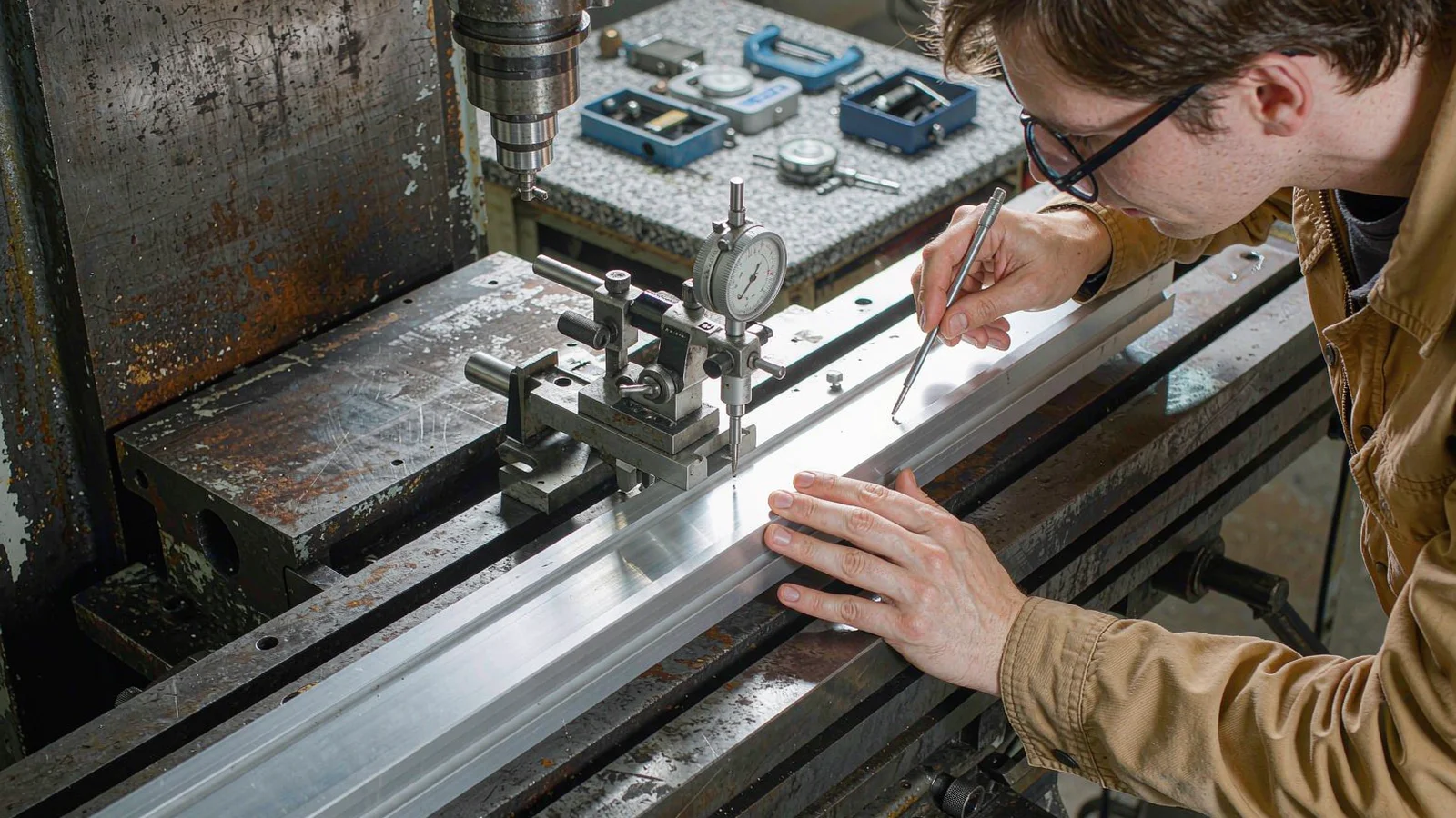
The straightedge method places a calibrated straightedge on or parallel to the stage bed, mounts a dial indicator or electronic probe on the moving carriage with its tip bearing on the straightedge, and records the reading as the carriage traverses. Because the indicator responds to the difference between the stage's actual lateral path and the straightedge surface, the raw trace contains both errors. The classical remedy is the reversal technique: after the first pass, flip the straightedge 180 degrees about its long axis (or swap its faces for a vertically measured straightedge) and repeat the traverse. The stage's straightness error repeats identically in both passes, while the straightedge's own error changes sign. Averaging the two traces cancels the artifact and isolates the stage; taking half the difference isolates the straightedge error, which is a useful check of its claimed calibration.
The method's honesty comes from its simplicity, and its limits follow from the same hardware. A straightedge long enough to cover the travel must be stiff enough not to sag measurably under its own support conditions, so long travels demand heavy, well-supported artifacts. Indicator direction must be square to the measured surface so cosine errors stay negligible, the tip radius should be large enough not to chatter across the surface finish, and the mechanical bracket must be stiff, because compliance between carriage and indicator turns vibration into phantom deviation. Within these constraints the method delivers micrometre-class straightness data cheaply, which is why it remains the standard first check on machine beds and medium-precision stages before any optical instrument is committed.
Autocollimator straightness measurement
An autocollimator measures angle, not displacement, which makes its use for straightness an integration exercise. A small mirror carriage sits on the stage or is walked along a surface plate in equal steps; at each position the autocollimator reads the mirror's angular tilt in the plane of interest. For a series of equal steps, each tilt multiplied by the step length gives the change in lateral deviation between adjacent positions, and cumulative summation reconstructs the straightness profile. This is why step length matters twice over: it sets the spatial resolution of the reconstructed curve, and it multiplies the angular reading to give displacement, so the autocollimator's angular resolution translates into better straightness resolution for the same instrument as steps become small.
The method excels on long travels—an autocollimator, unlike a straightedge, needs no artifact as long as the axis—and it resolves sub-micrometre straightness when steps are short and the environment is calm. Its discipline requirements are correspondingly specific. The mirror must ride square to the direction of travel so that yaw of the carriage does not leak into the measured tilt; the path between autocollimator and mirror should be free of thermal gradients that bend the optical path; and the data reduction must apply the cumulative-sum convention consistently, including the reference-line fit at the end. Integration is also the method's weakness in the presence of vibration and turbulence, which appear as slow drift in the reconstructed curve; repeat passes are the practical check, and a disagreement between passes means the environment, not the stage, is being measured.
Laser interferometer straightness optics and reversal technique
The laser interferometer measures straightness directly against an optical reference. A Wollaston prism mounted on the stage (or fixed in the beam path, with the reflector moving) splits the laser beam into two components with a fixed lateral separation; a straightness reflector returns them along a common path. When the moving optic translates laterally, the relative optical path of the two polarized components changes, and the interferometer converts that phase difference into lateral displacement against the straight reference line defined by the beam itself. Because the measurement is direct—no integration, no artifact of finite length—the method gives a continuous, high-resolution deviation curve in a single pass, at nanometre-class resolution over the travels typical of precision stages, and it is instrumentally continuous with the laser interferometer already used for along-axis positioning verification.
Two practices make the data trustworthy. First, alignment: the beam must stay within the linear range of the optics over the full travel, which means the Wollaston prism and reflector are squared to the axis carefully before the scan, with the measured shear kept small. Second, the reversal technique—here as with the straightedge, the reference can itself be imperfect. If the straightness reflector or prism is rotated 180 degrees about the beam axis between two passes, the stage's error repeats while the optics' residual error changes sign, and the averaged result separates the two. Air turbulence along the beam is the dominant environmental error for longer travels; shortening the exposed path, shielding the beam, and averaging multiple passes are the standard counters. Where straightness data must feed a formal error budget, this method's traceability and resolution make it the default choice for precision stage acceptance.
From straightness data to squareness, parallelism, and stacked-axis positioning
Straightness is rarely an end in itself; it is the input from which the geometric errors that matter are computed. Squareness between two axes is evaluated from the straightness traces of both axes: after fitting the reference lines to each axis's horizontal straightness data, the angle between those reference lines, measured against the nominal 90 degrees, is the squareness error. Straightness in the vertical plane similarly feeds parallelism evaluation between the stage travel and a machine datum such as the table surface. This is why measurement conventions matter downstream—squareness computed from straightness data taken with different reference-line conventions or filtering is not comparable between machines or between dates, and trend analysis on a production stage collapses.
On stacked-axis stages, straightness errors couple into positioning directly. If the Y carriage carries horizontal straightness deviation, then the X position of the end-effector depends on where Y is parked, so an X-positioning error map taken at one Y location does not hold at another. For two-axis stages the full geometric behavior is only described once horizontal and vertical straightness of both axes, their squareness, and the angular error motions are known together—the structure a volumetric error model consumes. Planning which of these terms the straightness measurements will feed, and at what uncertainty, belongs in the stage's error budget work rather than being improvised at measurement time.
Straightness error measurement is only as good as its conventions. ISO 230-1 gives the definition—horizontal and vertical deviation of a moving component's path within a minimum-width zone—but the practical number comes from choices made in the test plan: the plane, the measuring point, the reference-line algorithm, the sampling interval, and the filtering. A straightedge and indicator serve micrometre-class checks with reversal to remove the artifact error; an autocollimator integrates tilt into excellent long-travel profiles; and laser interferometer straightness optics with a Wollaston prism deliver direct, nanometre-class curves that feed squareness, parallelism, and volumetric error analysis with reversal separating optics from stage.
The working procedure is stable across methods: fix the conventions in writing, control the environment, record raw passes in both directions, apply a reversal where the reference is imperfect, and report the result per ISO 230-1 with its evaluation convention stated. Straightness data produced this way is comparable across machines and across years—and it is the data that squareness calibration and stacked-axis positioning analysis quietly depend on.
Written measurement plan naming the plane, axis, reference line convention, sampling interval, and any filtering applied before evaluation
Instrument record: straightedge calibration data or reversal result, autocollimator resolution and step length, or interferometer optics and environmental compensation settings
Raw deviation data along the travel in both directions, sufficient to reveal short-wavelength waviness rather than only a fitted curve
Reversal measurement record where the reference artifact error is separated, with both passes retained
Final straightness values for horizontal and vertical planes per axis, expressed per ISO 230-1, feeding squareness and volumetric error evaluations
FAQ
Questions engineers ask before selection.
What is the difference between straightness error and angular error motion?
Straightness error is a translational deviation: how far the trajectory of a point on the moving component departs from a straight line, expressed in micrometres within a plane. Angular error motions—pitch, yaw, and roll—are tilts of the moving component, expressed in angle. They are measured with different instruments (straightness methods versus tilt sensors or autocollimators) and both are needed to describe the geometric behavior of a stage; one cannot be inferred from the other because a carriage can translate laterally without tilting and vice versa.
Why is a reversal technique needed when measuring straightness?
Every straightness measurement is relative to a reference—the straightedge surface, or the optical line defined by the Wollaston beam and reflector. The reference itself is not perfect. In a reversal, the artifact or optic is flipped 180 degrees between two passes: the stage's error is the same in both passes, while the reference's own error changes sign. Averaging cancels the reference error and isolates the stage; taking half the difference quantifies the reference error itself. Without reversal, the result is a convolution of stage and artifact that cannot be separated after the fact.
Which reference line should be used when evaluating straightness data?
The two standard conventions are the line joining the first and last measurement points and a least-squares fit through the whole profile. Both are acceptable per ISO 230-1, but they give different peak-to-valley values for the same data, particularly for profiles with drift at the ends. The requirement is consistency: state the convention in the test plan and use it across machines and time, because squareness computed from straightness traces inherits whatever convention was used.
How do horizontal and vertical straightness affect stacked-axis positioning?
Each carriage's lateral deviations displace everything mounted above it. A horizontal straightness deviation on the lower axis of an XY stack shifts the upper axis's entire coordinate frame as the lower axis moves, so the effective X position of the end-effector depends on the Y coordinate and vice versa. Together with the axes' squareness, these deviations produce position-dependent errors that no along-axis calibration corrects. They must be measured and either compensated in the controller or included in the stage's positioning specification.
When is an autocollimator preferable to laser interferometer straightness optics?
The autocollimator is attractive when the artifact-free, stepwise scan suits the situation: long machine beds where a straightedge cannot cover the travel, or when the interferometer's beam path would be long and exposed to turbulence. It trades directness for reach—angular readings integrated over equal steps. The interferometer is preferred when nanometre-class resolution, a continuous profile, and instrumental continuity with positioning verification matter, and when the beam path can be kept short, shielded, and stable.