
A method that separates reference from machine
Diagonal comparison or reversal techniques whose math removes the reference instrument's error from the squareness result.
TECHNOLOGY / PRECISION STAGE METROLOGY
On a two-axis stage, squareness is the geometric error that no single-axis test can see: a fixed angle between the X and Y motion lines that turns every straight-line command into a bow across the workspace. This guide covers the measurements that isolate squareness—diagonal comparison, reversal with a reference square, straightness-based derivation—and how to compensate it.
Published
DIRECT ANSWER
Squareness error is the deviation of the angle between two axes of a stage from 90 degrees—typically a few arcseconds on precision machines, which translates to micrometers of cross-axis error over a 100 millimeter travel. Its signature is distinctive: a Y-coordinate that drifts proportionally to X travel no matter how well each axis measures individually, worst at the corners of the workspace and invisible to any single-axis accuracy test.
Three measurement routes dominate practice. Diagonal comparison measures the two workspace diagonals with a laser interferometer; their difference yields the squareness angle without an angular reference. Reversal with a calibrated square separates the instrument's own error from the machine's by measuring in two orientations. Straightness-based derivation measures each axis's straightness in the other axis's direction. Whichever route is chosen, the result becomes a fixed vertical-axis correction in the controller's geometry map—effective because squareness, unlike thermal drift, does not change with time.
ENGINEERING CONTEXT
A stage can post excellent single-axis accuracy certificates and still fail two-axis positioning tests, because squareness lives between the axes where axis-by-axis qualification never looks. Buyers discover it when a gage or camera reports position walking off a straight commanded line; builders discover it when a bidirectional grid test shows a systematic twist that error maps cannot remove. Because squareness is fixed in the machine geometry, an uncompensated value propagates into every measurement the machine ever makes—and a wrongly measured value, compensated in, does the same with more confidence.
Discuss your requirement ↗CRITICAL REQUIREMENTS
Diagonal comparison or reversal techniques whose math removes the reference instrument's error from the squareness result.
Squareness evaluated at the tool center point or sensor position, including offsets that scale the effect.
Squareness measured in both directions of approach, so reversal error is not folded into the geometry value.
A vertical-axis correction entry in the controller geometry map, with post-compensation verification on record.
BUYER MATRIX
Give every shortlisted supplier the same process definition and request configuration-specific proof.
| Method | Principle | Strengths | Limitations |
|---|---|---|---|
| Diagonal comparison | Measure both workspace diagonals; the difference reveals the squareness angle | No angular reference needed; fast with a laser interferometer | Assumes equal linear scales; setup alignment over long diagonals |
| Reversal with reference square | Measure a calibrated square in two orientations; reversal cancels its error | Direct traceability; also catches straightness contributions | Needs a high-grade square and repeatable fixturing |
| Autocollimator reversal | Reflect off the axis carriage in two orientations | High angular resolution; compact setup | Interprets local carriage angle; needs care over full travel |
| Straightness derivation | Sum each axis's straightness measured in the other's direction | Uses data already collected for straightness mapping | Cumulative uncertainty; misses rigid rotation between axes |
| Grid encoder / 2D test | 2D grid artifact measured across the workspace | Shows squareness with the full 2D error field | Artifact accuracy limits; interpretation needs care |
Model the error simply: the Y axis moves at 90 degrees plus a small angle alpha to the true perpendicular. Every millimeter of Y travel then adds alpha × travel of error in X. At 5 arcseconds—already a poor result for a precision stage—the cross-axis error reaches 2.4 micrometers per 100 millimeters of travel. Because the error is fixed in geometry, it does not scatter measurements; it biases them, consistently, in a pattern that repeats at the same workspace locations. That consistency makes it dangerous—it masquerades as machine accuracy—and fixable, because a constant is the easiest thing for a controller to correct.
Squareness also scales with working-point offsets. A probe or spindle mounted above the measurement plane sees the angular terms multiplied by that offset—yaw couples vertical offset into lateral error. Squareness must therefore be measured and compensated at the working point where the process happens, and a value quoted without its measurement plane is only half a specification.
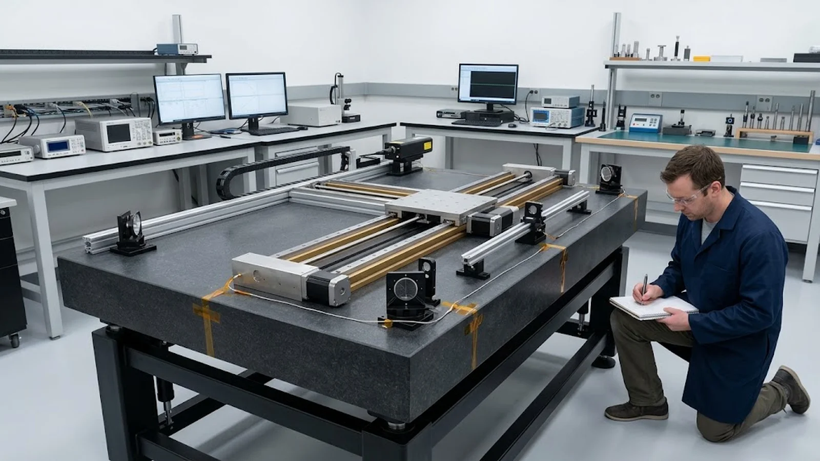
The diagonal method turns squareness into a length problem. Place a laser interferometer linear optics to measure one workspace diagonal from corner to corner, then repeat on the other diagonal. If the axes are perfectly square and the linear scales agree, the diagonals match; a squareness angle alpha produces a length difference of approximately L × alpha, from which alpha follows directly. The laser measures length—its most accurate mode—and the geometry does the conversion to angle.
The method's assumptions deserve respect. It presumes the two axes have equal, known scale factors, so a scale mismatch folds into the result; verify axis accuracy first or measure both diagonal directions to cancel it. Setup alignment over long diagonals is the practical bottleneck: the beam must stay on target across the full corner-to-corner stroke, which is exactly the alignment a stage with suspected squareness issues is least good at. Plan carefully, measure both travel directions, and average.
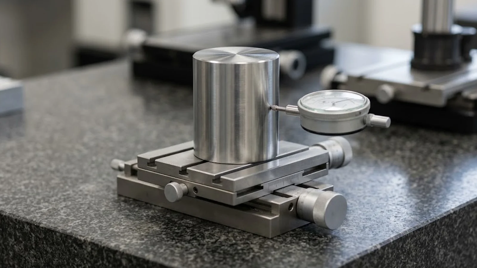
Reversal is the classical answer when a physical reference is used. A calibrated square sits on the stage and a probe or indicator reads its edge along Y; the square is then rotated 180 degrees and the measurement repeated. The square's own non-perpendicularity enters the two readings with opposite signs, the machine's squareness with the same sign—so the average cancels the reference error and the half-difference isolates the machine's value. The same arithmetic works with an autocollimator reflecting off a carriage mirror.
Reversal's rigor costs handling care. The 180-degree repositioning must not shift the reference by more than a fraction of the angle being measured, which at arcsecond level demands a repeatable fixture and a clean measurement plane. The payoff is traceability: the result chains directly to the square's calibration, and the reversal data doubles as a setup check—if the orientations disagree by more than the fixture repeatability explains, something moved, and the number is not ready to trust.
Because squareness is a fixed geometry error, compensation is a single vertical-axis term in the controller's geometric error model: X position is corrected by the measured angle times the Y coordinate, effectively shearing the coordinate system until the axes are orthogonal in the controller's arithmetic. Most CNC and motion controllers expose this as a squareness or perpendicularity parameter; on programmable stages, the same term enters the kinematic transform.
Compensation succeeds only on top of a correct measurement and a stable machine. Fix bearing and guide issues first—if the axes' straightness errors are large, a squareness term applied to them produces a workspace of sheared error maps that fit nothing. And document the value: the squareness entry belongs in the machine's geometry record with its date, method, working point and uncertainty.
Squareness earns its place in the acceptance protocol as a named line item, not a footnote inside a 2D accuracy plot. The specification should state the measurement method, the working point, the direction of approach and the uncertainty in arcseconds, and the acceptance test should include post-compensation verification: a bidirectional positioning or grid test across the workspace corners, where squareness residuals concentrate.
Keep squareness in the periodic verification plan with a relaxed interval. It is the most stable geometric error, but crashes, guide service and structural moves do move it, and a stage whose squareness drifted by a few arcseconds passes casual checks while its corner accuracy leaves specification. A diagonal spot-check once or twice a year is cheap insurance.
CONCLUSION
Squareness error sits between the axes, invisible to single-axis tests and proportional to travel, which makes it the geometric error most likely to contaminate two-axis positioning accuracy without an alarm. Diagonal comparison, reversal with a reference square and straightness-derived values each isolate it—provided the method separates the reference's error from the machine's and states its working point.
Compensate the validated value in the controller's geometry model, verify it at the workspace corners, and record it. Then the machine's accuracy certificates describe the machine rather than its mounting angle—and the one geometric error that never changes with time stops being the one nobody measured.
SOLUTION ROUTES
EVIDENCE CHECKLIST
FAQ
A squareness angle alpha between X and Y adds a cross-axis error proportional to travel: at 5 arcseconds, roughly 2.4 micrometers per 100 millimeters. The bias repeats at fixed workspace locations and is largest at the corners of the travel envelope.
Diagonal comparison suits stages with verified, equal axis scales and needs no angle reference. Reversal with a calibrated square offers direct traceability when a high-grade square and repeatable fixture are available. Straightness derivation works when the data already exists but carries cumulative uncertainty.
Rotating the square 180 degrees flips the sign of the square's own non-perpendicularity between the two measurements, while the machine's squareness keeps the same sign. Averaging cancels the reference term; the half-difference isolates the machine's angle.
Yes, effectively—a single vertical-axis correction term in the controller's geometric model shears the coordinate system to orthogonality. Compensation assumes the axes are mechanically sound; it corrects the angle, not bearing or guide defects.
Rarely, but not never. It is the most stable geometric error, yet crashes, guide maintenance and relocation can change it. A spot-check after such events, plus a periodic interval of one to two years, keeps the compensation valid.
AUTHORITATIVE SOURCES
TECHNICAL REVIEW
Send the application, critical parameters and any drawing or process information available.
Discuss your application ↗