
Scale placed near the working line
Encoder scale and readhead positioned at minimum practical offset from the functional axis, with the offset documented as a design parameter.
TECHNOLOGY / MACHINE DESIGN
The Abbe principle fails in most real machines because the encoder scale and the work point cannot occupy the same line. This guide explains how angular errors of the stage convert into positioning error through the Abbe offset, how to design and shorten the Abbe arm deliberately, and how to combine structural design with encoder selection and compensation to keep the error budget small.
Published
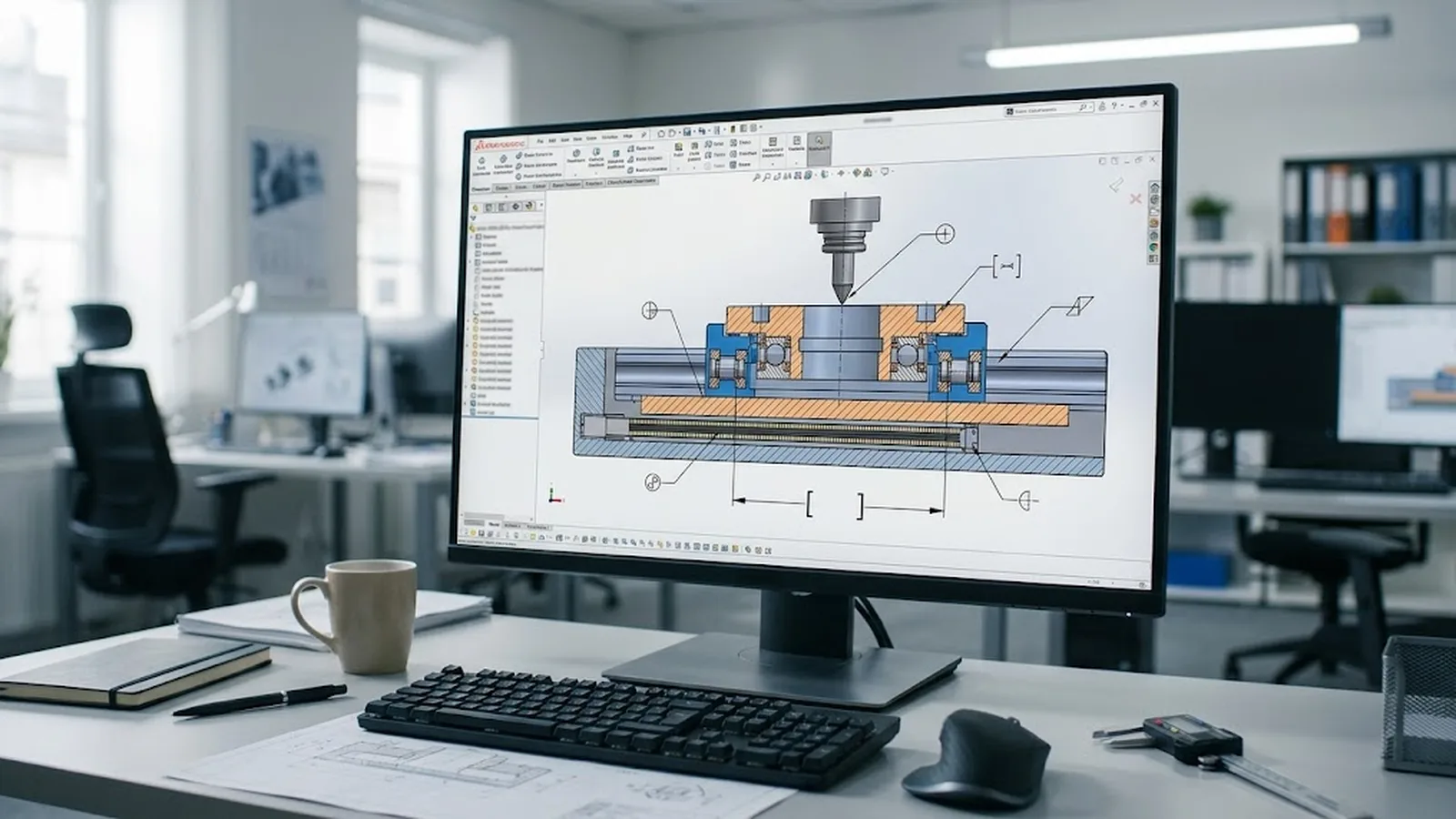
DIRECT ANSWER
Abbe error arises when the measuring line and the functional line of an axis are separated. In a linear stage the encoder scale sits offset from the work point by the Abbe arm; when the stage yaws, pitches or rolls by a small angle, that offset converts the angular error into a positioning error at the work point equal to offset times angle (in radians). A 50 mm Abbe arm with 2 arc-second yaw adds roughly 0.5 µm of error the encoder cannot see, because the encoder reports perfect straight-line position along the scale.
Minimization is a design sequence, not a single fix. First place the scale as close to the working axis as the mechanics allow, ideally in the same plane as the dominant motion error. Second, reduce the angular errors themselves with better guide geometry and straightness. Third, measure and compensate the residual with a second encoder or calibration mapping. Every micrometer removed from the Abbe arm shrinks the contribution of every angular error at once, which is why arm length is the highest-leverage variable in the machine's error budget.
ENGINEERING CONTEXT
Encoder datasheets quote straightness, accuracy and resolution along the measurement line, and machine builders budget with those numbers. The work point, however, is rarely on that line: spindles, probes, optics and workpiece tables stand tens or hundreds of millimeters from the scale. The error that matters is therefore not the encoder error but the encoder error plus the product of Abbe offset and stage angular motion—and the angular terms are frequently the largest and least documented contributors. Machines built around a fine encoder number but a casual scale placement routinely miss their positioning specifications, and the shortfall appears and disappears with load, wear and temperature in ways that resist calibration alone.
Discuss your requirement ↗CRITICAL REQUIREMENTS
Encoder scale and readhead positioned at minimum practical offset from the functional axis, with the offset documented as a design parameter.
Yaw, pitch and roll of the moving element measured or specified, because each multiplies the Abbe arm into positioning error.
The measuring loop follows the metrology frame with its own stiffness and thermal path, not the forces and heat of the drive chain.
Where geometry cannot eliminate the offset, a second measurement axis or error mapping covers the remaining contribution.
BUYER MATRIX
Give every shortlisted supplier the same process definition and request configuration-specific proof.
| Strategy | How it works | Strengths | Watch-outs |
|---|---|---|---|
| Shorten the Abbe arm | Move scale and readhead adjacent to the working axis in the layout | Reduces all angular error contributions simultaneously; no added complexity | Mechanical envelope limits; must be decided before the structure is fixed |
| Reduce angular errors | Improve guide straightness, bearing preload and carriage stiffness | Attacks the multiplier, not just the arm | Cost and damping trade-offs; needs angular metrology to verify |
| Dual encoder / dual path | Two scales or readheads at separated heights average yaw and pitch | Effective for large offsets; enables active correction | Added cost, space and control complexity |
| Mapping and compensation | Measure position error at the work point and correct in the controller | Removes repeatable systematic components | Cannot fix non-repeatability; thermal and load variation limit validity |
The Abbe principle states that the measurement should be collinear with the dimension being measured. A caliper violates it; a micrometer satisfies it. Linear stages almost always violate it, because the scale must sit where it can be mounted and protected while the functional point—tool, probe, optic or workpiece—stands above, beside or in front of the measurement line. The separation is the Abbe arm, and it turns every angular motion of the carriage into a positioning error at the point where work happens.
The arithmetic is simple and unforgiving. One arc-second is about 4.85 µrad, so each 100 mm of Abbe arm converts one arc-second of yaw into roughly 0.5 µm of positioning error. Guide straightness errors, bearing wear, load-induced deflection and thermal gradients all modulate the angular terms, which is why Abbe error at the work point is often several times larger than the encoder's own accuracy specification. The encoder is innocent: it reports position along the scale faithfully. The machine geometry adds the rest.
Arm length is decided in layout, before anything else is fixed. Identify the dominant functional point and route the scale toward it: for a stage carrying a centered workpiece table, the scale belongs under or beside the table centerline; for a gantry with an offset spindle, each axis needs its scale near that axis's functional line. Where the offset cannot be eliminated, orient the residual offset toward the direction with the smallest angular error—for example, keep the vertical offset small where pitch is inherently better controlled than yaw.
The Abbe arm is also a structure, not just a distance. The metrology loop that connects scale, carriage and work point should be stiff, short and thermally stable, decoupled from drive forces and motor heat that bend the structural loop. A 30 mm arm on a floppy bracket can contribute more error than a 60 mm arm on a rigid granite reference, so the design goal is a short arm on a stiff, thermally quiet metrology frame—both, not either.
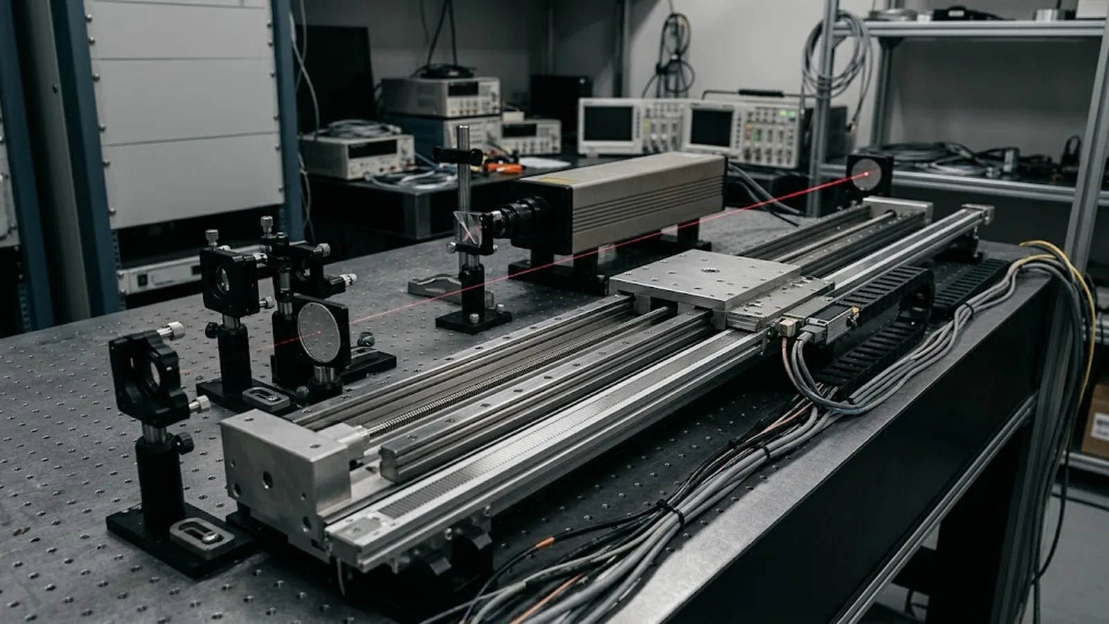
Because positioning error is offset times angle, the angle deserves the same engineering attention as the arm. Guide straightness sets the base angular trajectory over travel; bearing preload, carriage stiffness and load placement modify it. Measure yaw, pitch and roll over the full travel with an autocollimator, laser interferometer or electronic level, under realistic load, and record how they change with position and temperature. These profiles tell you where along the travel the Abbe contribution peaks and whether it is repeatable enough to compensate.
Improvements compound: halving the arm and halving yaw reduce the Abbe error to a quarter. For machines with tight budgets, the cheapest path is usually to spend mechanical effort where the arm cannot shrink—stiffer guides, better preload, symmetrical load paths—and reserve compensation for the repeatable residue.
When geometry reaches its limit, two paths cover the rest. A second encoder or dual readhead arrangement senses angular motion directly, letting the controller correct the work-point position in real time; this is standard in metrology-grade machines and increasingly common in production equipment. Alternatively, error mapping measures positioning error at the functional point across travel and load cases, and the controller applies the correction map—valid for the repeatable systematic component, invalidated by unmodeled thermal drift or load changes.
Verification must happen where the specification lives: at the work point, under representative load, not at the scale. If positioning accuracy is specified at the tool or probe, measure it there with an interferometer or artifact, and confirm the error budget's angular-Abbe line against reality. Machines verified only at the scale routinely surprise their owners at the point of use. SENFU application engineers review scale placement, offset and angular error data together when recommending encoder configurations, because the encoder selection is only as good as the geometry around it.
CONCLUSION
The Abbe arm multiplies every angular error of a stage into positioning error at the point where work happens, and it is set by layout decisions made before any datasheet matters. Shortening the arm, stiffening the metrology frame, reducing angular motion and compensating the repeatable residual form a design sequence that attacks the error from every available direction.
Verify at the work point, budget the angular terms explicitly, and treat scale placement as a first-order design parameter. With that discipline, the encoder's fine numbers translate into machine accuracy instead of being swallowed by geometry.
EVIDENCE CHECKLIST
FAQ
The perpendicular offset between the encoder's measurement line and the functional point where position matters—tool, probe, optic or workpiece. When the carriage rotates by a small angle, this offset converts the angular error into positioning error equal to offset times angle in radians.
One arc-second equals about 4.85 µrad, so each 100 mm of offset adds roughly 0.5 µm of positioning error per arc-second of yaw or pitch. A 50 mm arm with 2 arc-second angular error contributes near 0.5 µm, independent of the encoder's own accuracy.
Mapping compensates only repeatable systematic error. Angular motion varies with load, wear, temperature and position in non-repeating ways, so the compensation stays valid only within the measured conditions. Geometry—short arm and small angles—remains the foundation.
Two encoders at separated heights or positions sense angular motion of the carriage, allowing the controller to compute and correct work-point position in real time. It effectively shortens the Abbe arm in software at the cost of added hardware, space and control complexity.
As close as practical to the functional line of the axis, in a stiff and thermally stable metrology frame separated from drive forces and motor heat, with the residual offset oriented toward the direction of smallest angular error. The offset should be dimensioned on the drawing as a controlled parameter.
AUTHORITATIVE SOURCES
TECHNICAL REVIEW
Send the application, critical parameters and any drawing or process information available.
Discuss your application ↗