After a Stage Collision: Inspecting and Recovering an Optical Encoder System
A crash bends brackets, shifts scale alignment, and can leave an optical encoder that still counts but no longer measures truthfully. This guide walks through a structured post-collision inspection: electrical and alarm checks, mechanical damage assessment, signal-quality verification against pre-crash records, and the re-alignment and recalibration steps that decide whether the axis can be recovered in place or the feedback hardware must be replaced.
Published
DIRECT ANSWER
What should a buyer prioritize?
After a stage collision, treat the encoder as a suspected-damaged measuring instrument even if it still counts and reports no alarms. A structured recovery starts with electrical triage: read diagnostics and alarm history, back up parameters and error maps, and photograph the scale and readhead before touching anything. Then inspect mechanically—readhead gap and bracket stiffness, scale surface damage, mounting adhesive or screw integrity—using feeler gauges and the supplier's installation drawing rather than judgment by eye.
The decisive step is signal verification against documented baselines: compare quadrature amplitude, Lissajous circularity, and interpolation error on a calibrated stage travel against the commissioning record. A crashed axis frequently passes the smoke test while carrying a shifted air gap, a rotated readhead, or a bowed scale section that produces position error far outside the original specification. If signal quality and gap are restored to documented values and the scale surface is intact, re-alignment plus error-map refresh can recover the axis; visible scale scoring, adhesive fracture, or irreversible bracket deformation means replacement of the affected feedback components before recalibration is meaningful.
ENGINEERING CONTEXT
The decision starts with the real constraint.
The days after a collision are when the most expensive mistakes happen, and they are usually errors of omission rather than commission. The stage still moves, the encoder still counts, no alarm is latched—so production resumes, and nobody notices that the readhead bracket took a 0.05 mm set, or that the last 80 mm of scale is now bowed a few micrometers out of plane, or that the impact shifted the scale mount enough to change signal amplitude. The machine simply starts producing parts with a drift, a directional offset, or a repeatability degradation that no one can attribute, because the collision was never connected to the measurement chain. Optical encoders fail gracefully after impacts: the photodetector signals stay alive well outside their designed gap and alignment windows, so the electrical presence of a signal is not evidence of its quality. The engineering problem is that crash energy travels through exactly the structures that define encoder geometry—brackets, scale mounts, the mechanical loop between scale and workpiece—yet the damage is invisible without measurement. Without a structured inspection protocol, teams either replace expensive feedback hardware that was never damaged, or worse, recalibrate an axis whose scale or bracket is still deformed, baking the damage into the error map until it resurfaces months later as an untraceable accuracy loss.
Before any mechanical work, read and archive alarm history, diagnostic registers, and position-count behavior over full travel, and back up all encoder parameters, gain settings, and error-map tables so any recovery can be compared against the pre-crash configuration.
02
Mechanical inspection against the installation drawing
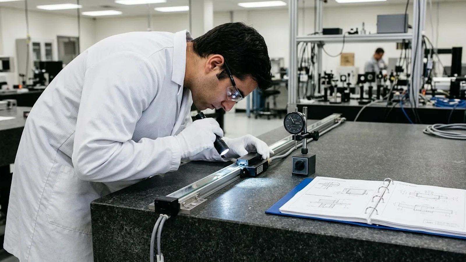
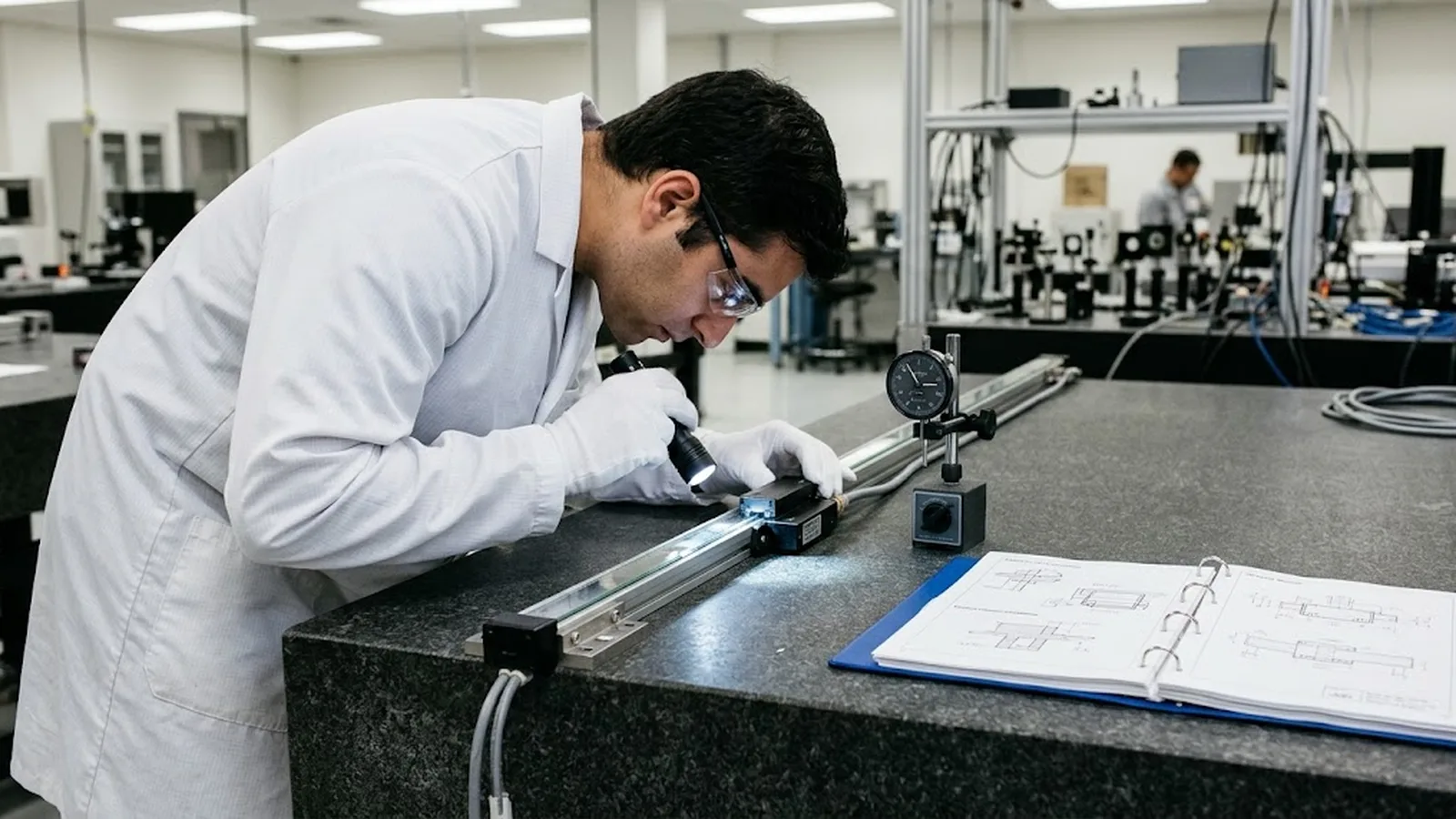
Measure readhead gap and lateral alignment with feeler gauges at multiple points along travel, inspect bracket and scale mounts for cracked adhesive, loosened fasteners, and permanent set, and examine the scale surface under oblique light for scoring, spalling, and deposit damage—not by eye but against the supplier's stated tolerances.
03
Signal-quality baselines from commissioning
Recover the commissioning record: quadrature signal amplitude and DC offsets, Lissajous figure circularity, subdivision error amplitude, and the original laser-interferometer or artifact-based accuracy trace. A post-crash measurement is only interpretable when compared to a documented baseline.
04
A written recovery decision gate
Define in advance which findings force component replacement (scale surface damage, adhesive fracture, bracket permanent set beyond tolerance) and which permit in-place recovery (gap and alignment restoration, parameter reload, error-map refresh), so the decision is evidence-based rather than schedule-driven.
BUYER MATRIX
Compare evidence, not feature labels.
Give every shortlisted supplier the same process definition and request configuration-specific proof.
Post-collision findings and the recovery path they dictate
Finding
Typical cause
Detectable by
Recovery path
Risk if ignored
Air gap outside specification
Bracket bending or permanent set from impact
Feeler gauge at multiple travel positions against installation drawing
Re-shim and re-align to specified gap; verify signal amplitude restored to baseline
Reduced signal margin; intermittent alarms at speed or with temperature change
Signal amplitude or Lissajous distortion
Readhead rotation, tilt, or contaminated/damaged scale window
Oscilloscope and interpolation diagnostics compared with commissioning record
Readhead alignment adjustment; scale cleaning per supplier procedure
Subdivision error growth, position jitter, and velocity ripple that recalibration cannot fix
Localized scale surface damage
Debris-driven contact, spalling, or scoring in the collision zone
Oblique-light visual inspection plus repeating position error localized to one travel region
Scale (or scale section) replacement; readhead inspection for debris damage
Periodic position error every scale period or a blind spot that corrupts counts
Scale mount adhesive fracture or bowed scale
Shock transmitted through the scale mounting substrate
Straightness measurement of the scale line; error signature repeating at the damaged span
Scale re-mounting or replacement with full re-alignment per installation procedure
Slowly drifting geometry error that defeats every error map applied over it
No measurable change found
Collision energy absorbed elsewhere in the machine
Full inspection protocol executed and documented with comparison to baselines
Return to service; file the record as evidence for insurance and future diagnosis
Undocumented assumptions that surface later as unexplained accuracy disputes
Why a surviving encoder is not a healthy encoder
Optical encoders tolerate far more geometric abuse than their specifications admit. The photodetector still produces quadrature signals with the readhead gap doubled beyond its design window; the interpolation electronics still count through misalignment that has already doubled the subdivision error; the absolute protocol still reports positions that are internally consistent and externally wrong. This graceful degradation is a virtue in service and a trap after a collision, because the usual failure signals—lost counts, latched alarms, a stage that refuses to close the loop—may simply never appear.
The physics of a crash concentrates damage exactly where the encoder keeps its geometry. Impact energy travels from the table or payload through brackets, mounts, and the structural loop, and the readhead bracket and scale mounting line are thin, cantilevered members with small cross-sections precisely because they must be stiff without loading the stage. A collision that leaves guide ways and drives visually intact can still impose a permanent set on a readhead bracket, rotate a readhead a fraction of a degree, or bow a tension-mounted scale strip. None of this is visible from outside the machine, and all of it changes the measurement. The inspection that follows a crash therefore has one purpose: to replace visual judgment with measurement against documented baselines.
Phase one: electrical triage and evidence preservation
Resist the urge to disassemble anything first. The initial pass is electrical and archival. Read out the encoder's diagnostic state—alarm and warning history, signal-amplitude and signal-margin indicators where the electronics provide them, and any interpolation error or position-error counters—and export this data before power cycles clear volatile history. Back up every parameter: gain and offset settings, reference-mark configuration, and above all any error-map or compensation table loaded into the controller, because the recovery decision later hinges on knowing what calibration state the machine was in when it crashed. Photograph the scale and readhead regions as found, before cleaning or adjustment, since deposit patterns and debris trails document how the collision actually progressed.
Then run the cheapest functional test that yields real information: command the axis through full travel at moderate speed and watch position counts, velocity feedback smoothness, and any warning flags. A count that skips or repeats identifies a hard fault immediately; smooth counting with no alarms tells you the feedback path is alive but says nothing about its quality, which is precisely the distinction the rest of the inspection exists to resolve. Machines with structured diagnostic reporting make this phase fast, and the alarm and fault monitoring guide describes the indicators worth exporting before and after any mechanical event. Where the collision tripped protection systems, the drive and controller logs should be exported in the same session so the impact speed and direction can be reconstructed for the mechanical inspection.
Phase two: mechanical inspection against the installation drawing
Mechanical inspection is a comparison exercise, not a visual one, and the reference document is the supplier's installation drawing with its stated gap, alignment, and fastener specifications. Start with the readhead: measure the air gap with feeler gauges at several positions along the travel—the gap that is correct at mid-travel can narrow near the ends if the bracket took a set—and check lateral alignment and any tilt dimension the drawing specifies. A gap that drifted but still sits within tolerance is a finding to record; a gap outside tolerance, or one that varies along travel when it was previously uniform, is evidence of bracket deformation that must be corrected before any signal work is meaningful.
Continue along the measurement loop. Inspect scale mounting fasteners for torque and witness-mark shifts, adhesive joints for crazing or partial fracture (common after shock, invisible under casual inspection), and the scale surface itself under oblique light for scoring, spalling, and localized deposits in the region where the collision occurred. On tensioned tape scales, check for wrinkles and lifting at the ends of the damaged span; on glass scales, chipping at edges and cracks radiating from mounting points matter even when the graduations still look intact. Finally, confirm the mechanical loop the encoder sits in: dial-indicator checks of bracket runout and stage-to-scale relative motion under load reveal whether the structure that carries the readhead still behaves as it did at commissioning. The geometry this phase protects is exactly the geometry described in the installation alignment errors guide, which catalogs how each mounting misalignment maps into position error.
Phase three: signal verification against the commissioning baseline
With gap and geometry restored to specification—or confirmed never to have left it—the decisive test compares signals, not impressions. On an oscilloscope or through the electronics' diagnostic interface, measure quadrature amplitude, DC offsets, and the Lissajous figure, and put the numbers beside the commissioning record. Amplitude that recovered to baseline after gap restoration is the normal good outcome. Amplitude that remains low with a correct gap points to contamination or surface damage on the scale; a Lissajous figure that is elliptical or off-center where it was once circular points to residual misalignment or electrical degradation. This comparison discipline is the same one used in routine signal-quality troubleshooting, and it is the only reliable way to distinguish a restored encoder from a merely counting one.
The final and most discriminating check is positional: measure the axis against a laser interferometer or a calibrated artifact over full travel and compare the error trace with the original acceptance report. Two signatures carry specific meanings. A subdivision-related periodic error that was previously within specification and now exceeds it indicates the readhead-scale interface never fully recovered. A localized bump in the error curve confined to the collision region indicates scale surface or mounting damage that no global compensation should be asked to hide. Distinguishing these cases before recalibration is what separates recovery from whitewashing—the error map applied afterward should represent residual system error, not frozen-in crash damage.
The recovery decision: restore, realign, or replace
The inspection data now supports one of three decisions, and the decision gate should have been written before the inspection began. If gap, alignment, and signals all verify within baseline after mechanical restoration, the recovery is in-place: re-tighten to specified torques, reload parameters, and perform a verification measurement to establish a fresh accuracy baseline—no error map from before the crash should be trusted across the event, even when signals look perfect, because bracket micro-settling can shift errors by amounts that matter. If signal quality cannot be restored to baseline by alignment and cleaning, but the scale surface is intact, readhead replacement plus realignment is the path. If the scale surface is scored or chipped, adhesive is fractured, or the scale line is measurably bowed, the affected scale hardware must be replaced and the axis realigned as a new installation, because no compensation strategy recovers a damaged measurement standard.
Two habits make the entire protocol affordable. First, file the recovery report the way an acceptance report is filed: measurements, photographs, decisions, and the new baseline, so the next anomaly on this axis starts from evidence rather than folklore. Second, use the recovery as a design review: a bracket that bent on first impact, a scale mount positioned in the debris path, or a gap setting with no margin against shock are selection and installation findings worth correcting, and the air gap and clearance setup guide explains how to set gap and alignment with the right margin in the first place. An encoder system that survives its next excursion either because the machine was fixed or because the design improved is the real deliverable of a post-collision inspection.
Measure the damage, do not assume it—and document what you measured.
A stage collision puts the encoder system in a state that its own electronics cannot report: the feedback keeps counting, the alarms stay quiet, and the only evidence of damage is a measurement quality that silently no longer meets specification. A structured response—electrical triage with parameter backup, mechanical inspection against the installation drawing, signal verification against commissioning baselines, and a written decision gate between in-place recovery and component replacement—turns an anxious day after a crash into an evidence-based procedure that protects both the machine and its calibration history.
The investment is modest: feeler gauges, an oscilloscope, the supplier's drawings, and the discipline to compare every post-crash reading against a documented baseline instead of a memory. Teams that inspect this way recover axes that can be recovered, replace only what is genuinely damaged, and put a fresh accuracy record into the machine's file—so the collision becomes a documented event with a bounded cost, not the unexplained beginning of a long accuracy dispute.
Pre-crash commissioning record: signal amplitudes, gap settings, subdivision error trace, and accuracy verification report
Post-crash diagnostics export: alarm history, warning counters, and position-count linearity over full travel
Mechanical inspection sheet: measured gap at defined scale positions, bracket runout, fastener torque status, and scale surface photographs
Post-recovery signal measurements compared side by side against the baseline record, with deviations quantified in supplier-specified units
Fresh accuracy verification (laser interferometer or calibrated artifact) after recovery, filed as the new baseline for the axis
FAQ
Questions engineers ask before selection.
The encoder shows no alarms and counts normally after a crash. Can we skip inspection and just recalibrate?
No. The absence of alarms demonstrates only that the signal path is functional, not that its geometry survived. A bent bracket or drifted gap can double subdivision error while counting flawlessly. Recalibrating over un-inspected mechanical damage risks baking a deformed measurement standard into the error map, and the damage resurfaces later as drift or directional error that is then very hard to attribute.
Which encoder components are most likely to be damaged by a collision?
In order of frequency: the readhead bracket (permanent set or bending), the scale mounting (loosened fasteners, adhesive fracture, bowed tape), the scale surface (scoring, spalling, debris-driven deposits in the collision zone), and the readhead itself (cracked housing, damaged window). The guide ways and drives usually absorb visible attention first, which is exactly why the encoder inspection is often skipped.
How do we check the readhead gap without special tools?
Feeler gauges and the supplier's installation drawing are the standard tools: measure at several points along travel rather than only at mid-stroke, because a deformed bracket can produce a gap that is correct in one position and out of tolerance elsewhere. Where the electronics provide a signal-amplitude or margin indicator, use it as a cross-check, but the gap value itself should be verified mechanically against the drawing.
After a successful recovery, can we reuse the pre-crash error map?
No. Even when signals verify to baseline, the impact may have caused micro-settling in brackets and mounts that shifts the error distribution. Perform a fresh accuracy verification after recovery and derive a new error map from it. The pre-crash map remains valuable as the comparison baseline that tells you how much the axis actually changed.
What should be in the recovery report?
The same structure as the inspection: diagnostic exports from before any intervention, photographs of scale and readhead as found, mechanical measurements against the installation drawing, signal measurements compared with the commissioning baseline, the decision taken and its justification, and the fresh accuracy verification that becomes the axis's new baseline. This record also supports warranty, insurance, and supplier-quality follow-up if component replacement was required.