
Coupling-tolerance budget
Convert the optical interface's alignment tolerance — mode-field size, channel pitch, angular tolerance — into required stage repeatability per axis, including the contribution from encoder feedback.
TECHNOLOGY / OPTICAL ENCODER TECHNOLOGY
Selecting and applying linear encoder feedback on active-alignment stages for silicon photonics packaging: resolution, throughput, environmental stability and verification evidence.
Published
DIRECT ANSWER
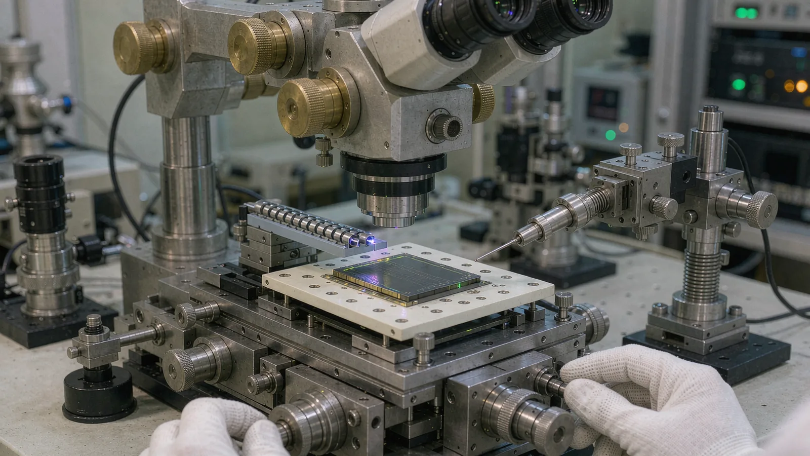
Active alignment in silicon photonics packaging moves a fiber array, collimator or second photonic die against a chip while an optical signal is maximized in the loop. The alignment stage's encoder feedback governs how precisely and repeatably the machine can execute those moves, how quickly it can find and re-find coupling, and whether recorded alignment positions can be trusted across temperature, time and handling. Encoder selection therefore starts from the coupling-tolerance budget: the mode-field dimensions and alignment tolerances of the optical interface define the position repeatability the stage must hold, and the encoder is chosen against that budget rather than against a nominal resolution figure.
Specify the encoder for the full packaging duty cycle — coarse approach, fine search,UV-cure hold, part change — and request configuration-specific evidence: repeatability at the working gap, noise at rest, speed capability for coarse motion, and the mounting and datum method that ties the encoder coordinate to the optical interface.
ENGINEERING CONTEXT
A photonics packaging line optimizes coupling on the first device, records the alignment coordinates, and finds the next device needs a re-search of several micrometers before the optical power recovers. The search costs seconds per channel and the yield loss shows up as handling and rework. The culprit is rarely the optimization algorithm alone: stage positioning repeatability, encoder noise at rest, thermal drift between alignment and cure, and Abbe offsets between the encoder scale and the optical interface all enter the loop between 'found' and 'reproducible'. Packaging engineers who treat alignment motion as a catalogue axis purchase often inherit exactly these gaps at production volume.
Discuss your requirement ↗CRITICAL REQUIREMENTS
Convert the optical interface's alignment tolerance — mode-field size, channel pitch, angular tolerance — into required stage repeatability per axis, including the contribution from encoder feedback.
Define coarse approach speed and travel, fine search step and range, hold stability during cure, and part-change overhead, since each phase stresses different encoder properties.
Request configuration-specific repeatability, noise-at-rest and speed data, plus mounting instructions that fix the encoder datum relative to the optical interface and workpiece.
BUYER MATRIX
Give every shortlisted supplier the same process definition and request configuration-specific proof.
| Phase | Motion character | Encoder property that dominates | Failure mode if inadequate |
|---|---|---|---|
| Coarse approach | Long travel at speed to bring fiber and chip near alignment | Maximum speed at configured resolution; edge-rate headroom | Lost counts or fault at traverse; slow approach inflates cycle time |
| Fine search | Small steps while optical power is monitored | Rest noise floor and step repeatability; resolution matched to coupling tolerance | Search oscillates or lands off-peak; step size cannot resolve the coupling curve |
| Peak capture and hold | Micro-move to the optimum, then hold while adhesive cures | Noise at rest and short-term drift of the encoder coordinate | Power drops during cure; recorded position does not reproduce after cure |
| Record and reproduce | Saving alignment coordinates for the next device or lot | Absolute or referenced position integrity; thermal stability of the scale datum | Recorded coordinates drift between sessions; repeated full searches |
| Part change | Stage retracts and re-presents the next device | Position integrity through interruption; startup recovery | Axis must re-home and re-datum on every cycle, adding overhead |
Silicon photonics coupling is unforgiving because the optical mode is small. A fiber-to-chip edge coupler or grating coupler has a mode-field diameter of a few micrometers or less, and coupling efficiency falls measurably for sub-micrometer lateral offsets — tighter still for high-numerical-aperture waveguides and for vertical coupling, where height and angular tolerances join the lateral ones. The packaging engineer's first task is to convert these optical tolerances into a motion budget: what fraction of the tolerance the stage repeatability may consume, split among the mechanical axes, the encoder feedback, thermal effects and the fixturing.
That budget immediately disciplines encoder selection. A stage that must re-find a coupling peak within, say, ±0.1 micrometer needs position repeatability comfortably better than that, which in turn requires an encoder whose noise at rest, periodic error and short-term drift are each small fractions of the budget — not merely a datasheet resolution finer than the number. Resolution and accuracy are different claims, and repeatability at the installed configuration is the one that determines whether the recorded alignment reproduces.
Abbe and datum geometry belong in the same budget. The encoder scale is mounted somewhere in the stage structure; if its measurement line is offset from the plane where the optical interface sits, small angular errors of the stage become lateral position errors at the coupling point. The supplier's installation drawing, the datum definition and the mechanical stack-up are part of the encoder decision, not an implementation detail to be settled after selection.
Packaging motion is not one motion. Coarse approach consumes travel and time and stresses speed capability: the encoder must keep counting reliably at traverse speed at the configured resolution, which is the same edge-rate arithmetic that governs any fast stage. Fine search stresses the opposite end: at rest and at micrometer steps, the noise floor and step-to-step repeatability determine whether the search algorithm sees a clean coupling curve or noise, and therefore how finely it can step and how confidently it can stop.
Peak hold and cure stress stability rather than dynamics. Between capturing the coupling optimum and the adhesive reaching handling strength, the recorded coordinate must hold: encoder noise at rest sets the visible jitter, while short-term drift of the scale datum — from motor and cure-lamp heating, fixturing and ambient — sets the invisible bias. Where UV cure sources or high-power illumination heat the assembly, the thermal map question from any precision stage applies here too, with the cure lamp as a heat source the original stage design may not have anticipated.
Record-and-reproduce is the phase that turns alignment into production. Whether the axis uses incremental feedback with a defined homing routine or absolute feedback that recovers position at startup, the packaging machine must be able to return to recorded coordinates across part changes, interruptions and shift boundaries. Absolute encoders remove the re-homing overhead and the risk of a mid-process power cycle invalidating the datum; incremental routes remain fully viable where the homing routine is part of the documented cycle. The choice should be made against the machine's interruption scenarios, not by preference.
Before shortlisting readheads, answer these for the specific packaging process:
Photonics packaging machines concentrate delicate mechanics, optics and heat sources in a small volume: motion motors, UV cure lamps, optical power monitors and temperature-controlled chucks share the same frame. The encoder's installed behavior depends on that environment — signal margins through the cable route near noise sources, mounting compliance between scale and structure, and the thermal path from the scale datum to the optical interface. The supplier's installation tolerances (readhead gap, scale alignment, cable strain relief) are part of the repeatability budget and should be verified at commissioning, not assumed.
EMC discipline is not optional in a machine that also switches motors and drives cure sources. Route encoder cabling away from motor and lamp drive conductors, honor shield termination instructions, and verify signal margins on the oscilloscope during worst-case operation — cure lamp firing, motors at full current — rather than with the machine idle. The cost of an afternoon of signal verification is small against the cost of chasing intermittent count faults in production.
Finally, tie the encoder coordinate to the optical interface by measurement, not by drawing. After integration, execute a reproducibility test with production fixturing: align a device, record coordinates, change parts, re-align and re-record, across several cycles and thermal states. The spread of recorded coordinates — not the datasheet repeatability — is the number that predicts whether the machine can skip or shorten its searches in production. Where the spread exceeds the budget, the diagnosis proceeds through the same elements as any precision axis: fixturing, Abbe geometry, thermal drift, then encoder noise.
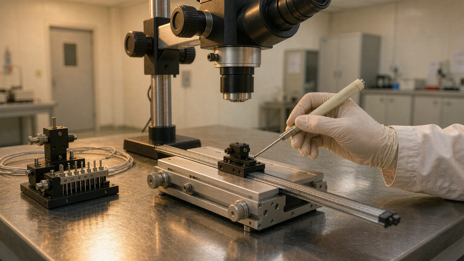
Accept the encoder on evidence collected the way the machine will run. Useful qualification evidence includes: rest noise floor per axis at the working configuration, measured with the machine's own drive and cabling; step repeatability over the fine-search range; repeatability of return to a recorded coordinate across part changes and thermal cycles; and speed verification at the traverse profile, including acceleration transients. Each test is short, and together they close the gap between component specifications and machine behavior.
For procurement, put the tolerance budget and the verification plan in the RFQ. State the optical interface's alignment tolerance, the duty cycle, the cure and thermal environment, the interruption scenarios and the target cycle time, and ask each supplier to identify the exact readhead, scale, resolution and interface in its response, with the evidence it commits to. This is the same configuration-specific discipline that governs any precision encoder purchase, applied to a machine where the position budget is set by an optical mode rather than a mechanical fit.
SENFU's application engineering supports this review for photonics packaging stages using SMG-series feedback: from the coupling-tolerance budget and duty-cycle definition through mounting and datum planning, to the repeatability and speed verification that should accompany machine acceptance. The result is an alignment machine whose recorded positions mean what production expects them to mean.
CONCLUSION
In silicon photonics packaging the encoder feedback defines whether an alignment found once can be found again: the coupling-tolerance budget sets the position repeatability required, and the encoder must deliver it across the whole packaging duty cycle — fast coarse approach, fine noisy-tolerant search, stable hold through cure, and reliable return to recorded coordinates after part changes. Selection, mounting, thermal and EMC integration and production-representative verification are one discipline.
For a SENFU application review, send the optical interface tolerance, the stage travel and duty cycle, the cure and thermal environment and the interruption scenarios. SENFU can propose SMG-series feedback configurations with the mounting, datum and verification evidence needed to close the position budget before the machine reaches the production floor.
SOLUTION ROUTES
EVIDENCE CHECKLIST
FAQ
Start from the coupling curve: the lateral, vertical and angular offsets over which the optical power stays within its acceptable loss define the position budget. Reserve a fraction for the stage feedback and split the rest among mechanics, fixturing and thermal effects. The encoder's repeatability and noise at rest — at the installed configuration, not the datasheet resolution — must be a small fraction of its share.
Absolute feedback removes re-homing after every interruption and protects recorded coordinates through power cycles, which matters when cycle time is dominated by repeated searches or when the machine must resume mid-process. Incremental feedback remains viable where homing is a documented, fast part of the cycle. Decide against the machine's interruption scenarios and cycle-time budget, not by preference.
Between peak capture and cure completion, the assembly can move: cure-lamp heating, fixturing relaxation and stage drift each shift the interface. Encoder noise at rest sets the visible jitter; short-term drift of the scale datum sets the bias. Map the thermal sources in the assembly and verify hold stability with the cure lamp firing, then decide whether the remedy is thermal, fixturing or feedback-related.
The reproducibility of a recorded coordinate across part changes and thermal states is a machine-level figure, built from stage repeatability, encoder noise and drift, Abbe geometry and fixturing. It must be measured on the integrated machine with production fixturing; a component datasheet value alone cannot predict it. The measured spread is the number that determines whether searches can be shortened or skipped.
Route encoder cabling away from motor and cure-lamp drive conductors, follow the supplier's shield termination instructions, and verify signal margins on an oscilloscope during worst-case operation with motors at full current and the cure source firing. Intermittent count faults traced to EMC in production cost far more than the commissioning verification.
Send the optical interface type and alignment tolerance, stage travel and maximum speed, the fine-search step and range, the cure and thermal environment, interruption scenarios and the target cycle time. SENFU application engineering can propose feedback configurations, mounting and datum guidance, and a verification plan matched to the packaging process.
AUTHORITATIVE SOURCES
TECHNICAL REVIEW
Send the application, critical parameters and any drawing or process information available.
Discuss your application ↗