Device geometry
Define lines, gaps, openings, beams, membranes, gradients and profile requirements.
APPLICATION / MEMS PROTOTYPING
Choose DMD direct write for MEMS prototypes by matching layout iteration, feature geometry, alignment, substrate, resist and inspection needs.
Published
DIRECT ANSWER
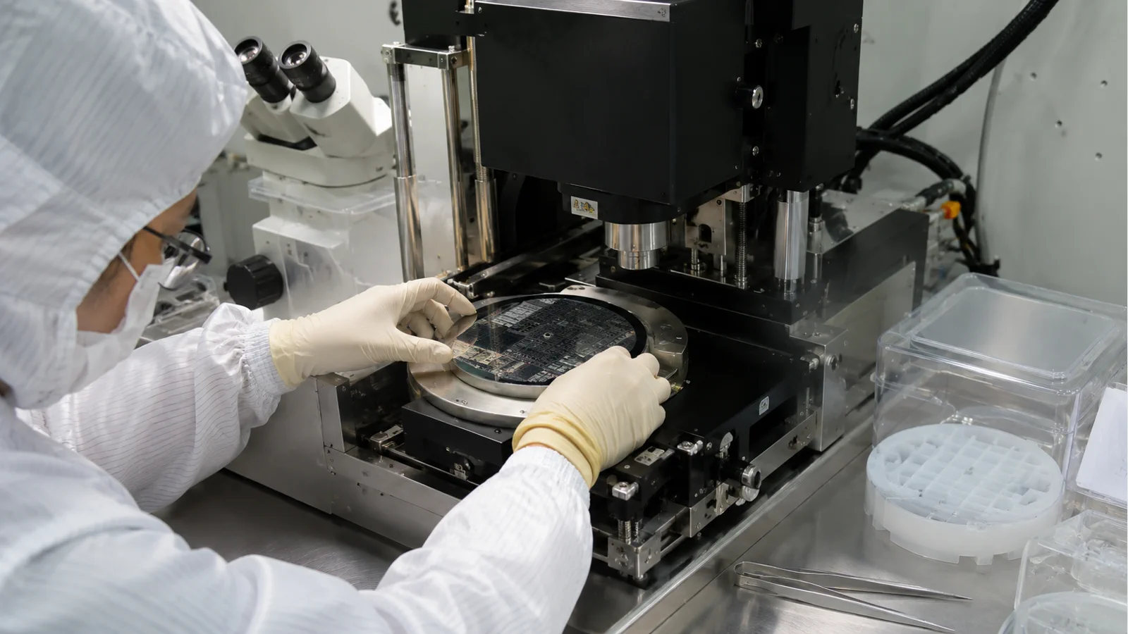
DMD maskless lithography is a strong MEMS prototyping route when layouts change often, multiple layer combinations must be explored and a physical mask would slow learning. Select the system from feature geometry, substrate size and thickness, resist, wavelength, overlay, grayscale or relief needs, inspection and iteration time. ZML10A is positioned for compact laboratory R&D and MEMS; ZML100A adds active autofocus and overlay-oriented control; ZML200A covers up to 8-inch substrates in the documented family.
Maskless does not mean process-free. A MEMS buyer still needs a resist and development window, alignment marks, focus strategy, substrate handling and a measurement plan. Qualify a representative device coupon and reserve electron-beam exposure for critical nanoscale features when a hybrid flow is justified.
ENGINEERING CONTEXT
MEMS development moves between beams, membranes, electrodes, wells and release structures. The tool must support fast layout iteration without losing alignment, profile or process traceability across the layers that matter to device behavior.
Discuss your requirement ↗CRITICAL REQUIREMENTS
Define lines, gaps, openings, beams, membranes, gradients and profile requirements.
Specify silicon, glass or polymer, thickness, flatness, resist and development.
Plan marks, coordinate handoff, overlay and inspection between exposures.
Compare design turnaround, setup, exposure, metrology and process learning.
BUYER MATRIX
Give every shortlisted supplier the same process definition and request configuration-specific proof.
| Need | DMD evidence | Question |
|---|---|---|
| Layout changes | File-to-pattern workflow and revision time | How quickly can the next geometry be tested? |
| Profile | Grayscale/relief coupon and measurement | Can the tool make the required topography? |
| Alignment | Marks, overlay map and coordinate transfer | Will electrodes and membranes line up? |
| Sample | Size, thickness and handling drawing | Can the actual wafer or die load safely? |
| Critical size | CD and dense-feature result | Does a nanoscale layer need EBL instead? |
List the design variables that will change: beam width, gap, anchor, electrode, membrane opening, etch window or release geometry. A DMD workflow is valuable when the team can revise the layout and expose a new coupon without ordering a new mask. Quantify the time from CAD revision to inspected sample and include design conversion, coating, exposure, development and measurement.
A prototype tool should also support traceability. Keep layout revision, recipe, substrate, resist, dose, focus, alignment marks and inspection image together. This lets the team tell whether a device change came from the layout or from process drift.
Separate binary features from profile-sensitive structures. Lines, gaps and openings may need uniform CD, while lenses, ramps, membranes or fluidic relief may need grayscale dose control and profile metrology. Record the smallest and largest geometry, equal line/space, edge slope, height or depth and the inspection instrument.
If the device has a nanoscale junction or dense critical feature, mark that layer for a separate technology review. DMD can handle broad microscale patterns efficiently, while EBL may be reserved for critical features. A hybrid process is useful only when marks, coordinate transfer and resist handoff are planned.
ZML10A is positioned as a compact R&D system for rapid prototyping, MEMS and microfluidics with documented 385/405 nm exposure and up to 4-inch samples. ZML100A adds active autofocus and motorized objective control for workflows that need focus and overlay support. ZML200A is the family route when the project needs up to 8-inch substrates.
Compare the platform using the same device, resist, overlay and throughput conditions. The largest sample is not the only driver; objective working distance, thickness, flatness, mark visibility, focus variation and service access may be more important for a MEMS stack.
MEMS layers often mix a large device outline with small electrodes, marks or release windows. Place alignment marks near the critical layer and protect them through the resist and etch sequence. Define wafer orientation, chuck datum, file origin, scale and transform. A mark map is a practical interface between design, exposure and metrology.
Measure overlay on the actual substrate and topography. A mark that is visible on a flat coupon may disappear under a thick resist or after a deep etch. Keep a record of which layer owns each mark and how it is located by the selected objective or alignment routine.
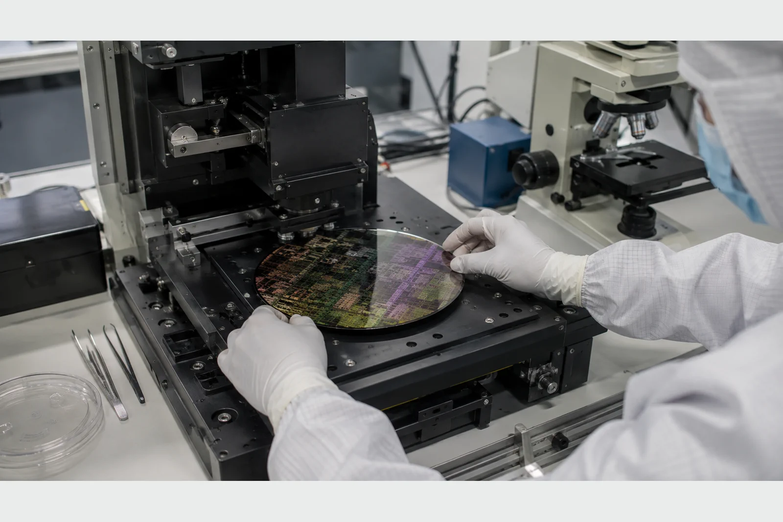
Specify substrate material, thickness, bow, surface treatment, resist, bake, wavelength, dose and development. MEMS flow can add hard masks, etch, metal lift-off, bonding or release steps that change the required resist profile. The supplier should demonstrate the process result or identify the development work still required.
Track contamination and handling. A prototype may move between coating, exposure, inspection and etch without the controlled packaging of a production fab. Define cleaning, storage, edge exclusion and operator steps so the process learning is reproducible.
For MEMS, the useful metric is often the time to an inspected, measurable device rather than exposure seconds. Record file preparation, alignment, focus, exposure, development, inspection and rework. Compare sparse and dense patterns because DMD exposure time and process risk can change with pattern area and dose.
Ask for a representative weekly workload and a sample recipe. Include objective, resolution, wavelength, pattern density and operator steps. A tool that is fast on a small coupon may not deliver faster learning if every thick-resist layer requires lengthy focus or inspection.
Use a coupon that includes beams, gaps, electrodes, openings, alignment marks, profile structures and a dense feature. Measure CD, overlay, profile, defects and repeatability with the facility's instruments. Keep the same recipe and coordinate system across design iterations so results remain comparable.
Agree what is a platform acceptance result and what is a device-development result. The former should be repeatable at installation; the latter may evolve as the process matures. Document the handoff to an EBL step if critical features are split between tools.
Provide layout examples, feature and profile targets, sample matrix, resist, wavelength, overlay, inspection, iteration time, environment and service constraints. Ask for configuration-specific results, file workflow, alignment method, throughput conditions and an acceptance coupon.
SENFU can match a MEMS prototype requirement to the ZML family and identify when a hybrid DMD/EBL process is more practical. The output should be a documented learning loop that the research team can repeat and the procurement team can defend.
MEMS iteration is valuable only when one design change can be separated from process drift. Keep the same wafer orientation, chuck datum, mark map, resist preparation, exposure file and inspection coordinates while changing the geometry under study. Record coating lot, bake, dose, focus, development and operator. If a feature improves, the team should be able to explain whether the improvement came from the layout or from an uncontrolled process change.
Define a small control coupon that travels with each prototype run. Include a line/space feature, an alignment mark, a profile structure and a representative device fragment. Trend CD, overlay, profile and defect observations against the control. When a layer moves to EBL or another facility, transfer the coordinate and mark record with the job. This creates a practical bridge from university-style iteration to a reproducible engineering process and gives procurement evidence for the next tool decision.
Use the control record to decide when a prototype is ready for the next unit operation. A release or bonding step may magnify a small overlay or profile error, while a large device outline may hide a local defect. Set a review gate for the critical layer, archive the inspected coupon and record any process-development exception. The gate does not slow experimentation; it prevents an untracked change from being mistaken for a better lithography platform.
CONCLUSION
DMD maskless lithography is valuable for MEMS when it shortens layout-to-sample cycles without losing alignment, profile or traceability. Choose the ZML platform from the complete sample and process envelope and qualify a representative coupon.
SENFU can review the MEMS layout, substrate, resist and inspection plan and identify whether ZML10A, ZML100A, ZML200A or a hybrid route closes the requirement.
SOLUTION ROUTES
EVIDENCE CHECKLIST
FAQ
It removes the need to fabricate a new physical mask for every layout revision, which can shorten the path from CAD change to inspected prototype.
Compare sample size, autofocus/overlay needs, thickness, geometry, resist and workload. ZML10A is positioned for compact R&D, ZML100A adds active focus and ZML200A covers larger samples.
It is suited to microscale and profile patterns; critical nanoscale features may need EBL or a hybrid flow.
Include device geometries, dense features, alignment marks, profile structures and the metrology needed to diagnose the process.
Send layouts, feature/profile targets, substrate, resist, wavelength, overlay, inspection, iteration time and environment.
AUTHORITATIVE SOURCES
TECHNICAL REVIEW
Send the application, critical parameters and any drawing or process information available.
Discuss your application ↗