
Field grid calibration data
Per-field offset, scale, rotation and distortion measured in a calibration pass and stored with timestamps for drift tracking.
TECHNOLOGY / MASKLESS LITHOGRAPHY
Stitching quality in maskless lithography is decided where adjacent write fields meet, and static calibration alone cannot hold it across a full substrate. This guide explains how real-time error feedforward—pre-measured field corrections combined with live stage and beam data—keeps field placement error inside the process window while the job is running.
Published
DIRECT ANSWER
In maskless lithography, the pattern is written field by field, and every boundary between two fields is a potential stitch defect. The error that matters at those boundaries is field placement error: each field lands with its own offset, scale, rotation and—on many tools—keystone distortion relative to the ideal grid. Feedforward correction means measuring or predicting that error per field and applying the inverse correction to the beam deflection and stage commands before the field is exposed, so the correction arrives ahead of the writing instead of after inspection.
A real-time feedforward chain has three layers. Static grid corrections, measured in a calibration pass, remove the repeatable part of field placement error. Interpolated corrections, built from live encoder readings during the job, absorb slow drift between fields—thermal growth, air-pressure shifts, stage geometry change with position. Residuals that move too fast for the stage loop are taken out by the beam deflection path, which responds in microseconds. Together they hold stitching error near the metrology floor for whole-substrate jobs.
ENGINEERING CONTEXT
A tool calibrated on a Monday grid can still stitch poorly by Wednesday afternoon. Field placement error is not a constant to be measured once: it drifts with substrate holder temperature, changes sign across the stage travel, and couples to the duty cycle of the job itself. Feedback-only strategies discover each stitch error after it is written—at best, a correction for the next substrate; at worst, a scrapped run. The engineering problem is therefore not measuring stitching error but getting the correction ahead of the exposure, which is exactly what feedforward architectures exist to do.
Discuss your requirement ↗CRITICAL REQUIREMENTS
Per-field offset, scale, rotation and distortion measured in a calibration pass and stored with timestamps for drift tracking.
Encoder readings available to the pattern generator with latency low enough to matter during writing.
Beam deflection or a second fast axis able to absorb residuals within one field exposure, independent of stage bandwidth.
Temperature and pressure sensors on the metrology path so interpolated corrections track causes, not just symptoms.
BUYER MATRIX
Give every shortlisted supplier the same process definition and request configuration-specific proof.
| Strategy | How it works | Strengths | Limitations |
|---|---|---|---|
| Static grid calibration | Pre-measured per-field corrections applied from a stored table | Removes repeatable error; simple to validate | Blind to drift between calibration and job |
| Encoder-interpolated feedforward | Live encoder readings drive position-dependent corrections between fields | Tracks thermal and geometric drift in real time | Needs low-latency data path and validated model |
| Beam deflection feedforward | Fast deflection channel applies per-field correction during exposure | Microsecond response; absorbs what the stage cannot | Correction range limited by deflector optics |
| Feedback after inspection | Stitch error measured on written wafers, corrections updated for the next run | Ground truth on the real process result | Too late for the current substrate; slow convergence |
| Environmental hardening | Tighter temperature and pressure control reduce the drift itself | Attacks the cause; benefits every error path | Cost and physical limits; never zero |
Each write field inherits error from three stacked sources. The stage positions the field center with its own accuracy and repeatability; the substrate holder deforms and expands with temperature; and the deflection optics map the beam with residual scale, rotation and distortion of their own. Stage and holder errors are position-dependent—the same field number lands differently depending on where it sits on the travel—while deflection errors are stable in the beam frame and appear as a fixed distortion pattern in every field.
The composite signature is what stitching sees: two adjacent fields written minutes apart, each with slightly different placement transforms, produce a seam whose mismatch is the difference of their errors. Because the components have different time constants—deflection distortion stable for hours, holder drift following thermal time constants of minutes to hours, stage error following position—the composite error is best attacked piecewise, with each correction channel handling the component whose timescale matches its bandwidth.
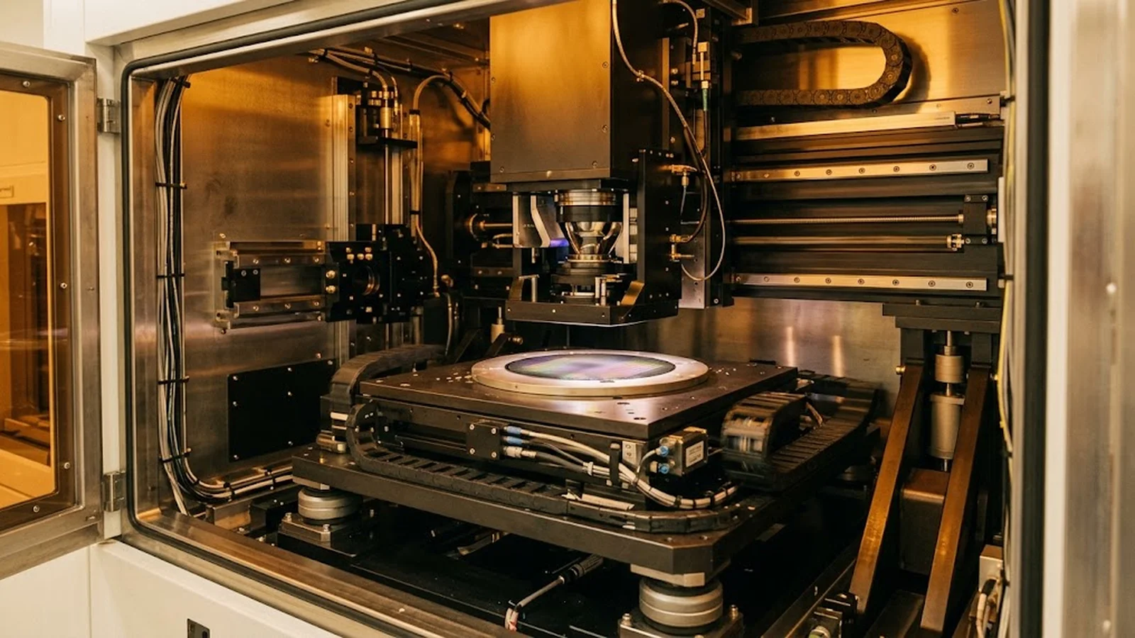
The foundation is a calibration pass that writes alignment-rich marks at every field boundary or corner, measures the written grid against the ideal, and solves a per-field correction: translation, gain, rotation and, where the optics support it, keystone terms. This grid correction removes everything repeatable, which on a thermally settled tool is usually the majority of stitching error.
Two disciplines make the static layer trustworthy. First, measure the grid under the same thermal state the production job will see—a grid calibrated cold degrades within the first hour of writing as the tool warms. Second, timestamp and archive each grid: comparing successive calibrations reveals which components are drifting and how fast, and that drift rate is the specification the next correction layer must meet.
Between calibration and the fields written hours later, the world moves. Encoder-interpolated feedforward closes that gap by correcting each field from live data: as the stage parks at or passes each field position, current encoder readings feed a model that updates the field's placement correction. The model is built from the archived grids—correction value regressed against stage position and holder temperature—so the live reading is mapped to the correction the calibration history says applies.
The critical specification is latency. If encoder data reaches the pattern generator tens of milliseconds before the field starts, position-dependent error is corrected cleanly; if it arrives after the field is written, the architecture degenerates to feedback. The data path—encoder interface, controller, pattern generator—must publish a measured end-to-end latency, and the write sequence must guarantee a stable position sample inside that window before the field trigger fires.
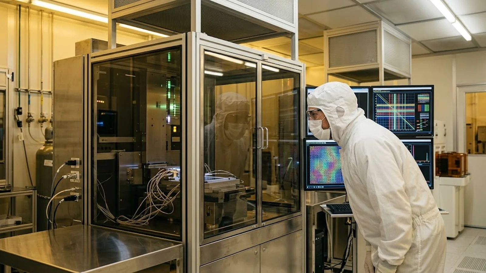
Whatever the first two layers leave lands inside the field, where the deflection channel can still act. Per-field correction values—residual offset and distortion after the grid and interpolated updates—drive the beam deflection during exposure, repositioning sub-elements of the pattern at deflector speed rather than stage speed. This is what absorbs the fast tail: stage settle residuals, encoder quantization at field corners, and slow stage motion during write-on-the-fly writing.
The deflection layer has its own error and its own range. Corrections beyond a few percent of the field size stress deflector linearity, and the deflector's own calibration drift must be covered by the static grid. Keep the correction hierarchy explicit: stage and holder errors in the field placement path, deflector errors in the deflection path, and a documented handoff so no error is corrected twice—or not at all.
Feedforward earns trust the same way any metrology system does: by measured evidence against stated conditions. The qualification set below covers the failure modes that matter—a stale grid, a slow data path, a deflector running out of range—and doubles as the ongoing maintenance check, since drift behavior changes as tools age and environments shift with the seasons.
Run the full set after commissioning, after any change to the data path or optics, and at intervals long enough to expose seasonal drift. A tool that passes all four has a stitching architecture that is understood, not just adjusted.
CONCLUSION
Field stitching error is a moving target: deflection distortion stable for hours, holder drift following thermal time constants, stage error following position. Static grids, encoder-interpolated corrections and deflection feedforward each cover the part of that spectrum their bandwidth can reach—and together they hold seam error near the metrology floor for entire jobs rather than for the first hour.
Qualify the chain as an architecture: a measured grid under production thermal state, a published encoder-to-deflection latency, corrections inside deflector range, and drift tests across real duty cycles. Then stitching stops depending on when the job runs and starts depending on design—which is the only dependency a production schedule can live with.
SOLUTION ROUTES
EVIDENCE CHECKLIST
FAQ
Applying the inverse of each field's expected placement error to the beam deflection and stage commands before the field is exposed. It contrasts with feedback strategies that measure stitching error only after writing, when the correction can only help the next substrate.
Driven by measured drift, not a fixed interval. Compare archived grids over time; when drift between calibrations approaches a fraction of the stitching budget, shorten the interval—and rely on encoder-interpolated feedforward to cover drift between calibrations.
Encoder-interpolated feedforward only works if the position reading reaches the pattern generator before the field is exposed. If latency exceeds the field trigger timing, corrections apply to the past and the system degrades to reactive feedback.
No. Deflection handles fast, small residuals during exposure. Placement error from stage position and holder drift is corrected in the field placement path; deflection corrections beyond its linear range introduce their own distortion.
It increases the load on the deflection layer, since the stage is moving while fields are written and the deflector must absorb continuous residual motion. The static grid and interpolated layers still handle position-dependent and thermal error; the latency budget becomes even tighter.
AUTHORITATIVE SOURCES
TECHNICAL REVIEW
Send the application, critical parameters and any drawing or process information available.
Discuss your application ↗