
Signals inside the interpolation window
Sine and cosine amplitudes within the specified range at the electronics input, so the interpolator operates in its linear, low-error region.
TECHNOLOGY / ENCODER INTERPOLATION
Optical encoders report position far finer than the physical scale pitch by interpolating between sinusoidal signals. This guide explains how sine/cosine interpolation and signal subdivision work, what sets the subdivision factor limit, and how signal quality, pitch and electronics decide the final resolution and its accuracy.
Published
DIRECT ANSWER
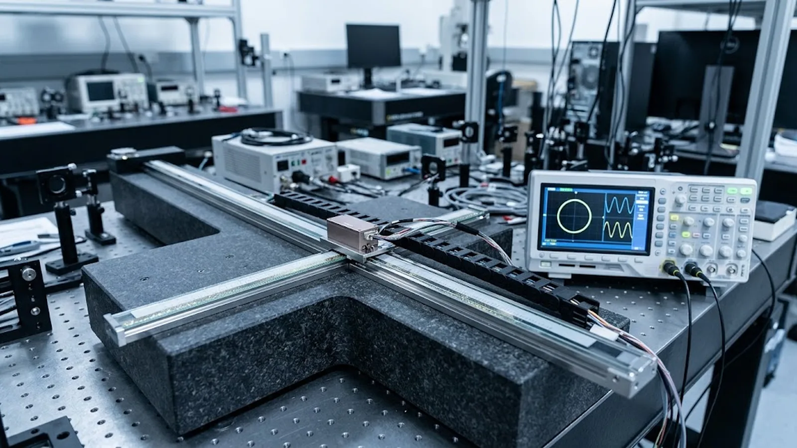
An optical encoder readhead produces two sinusoidal signals, sine and cosine, one full period per scale pitch. Because the two signals are shifted 90 degrees in phase, every position within one pitch corresponds to a unique point on the circle they trace together. Interpolation electronics measure the phase angle of that point and subdivide each period into many equal steps, so a 20 µm scale pitch can deliver a reported resolution hundreds or thousands of times finer than the pitch itself.
The subdivision factor is not free accuracy. It is limited by signal amplitude, DC offset, amplitude balance between channels and harmonics, and each imperfection maps directly into a periodic position error. High subdivision therefore demands clean signals and correct gain and offset setup, which is why interpolated resolution must always be judged together with interpolation error, not quoted as an accuracy figure on its own.
ENGINEERING CONTEXT
Datasheets routinely quote resolutions far below the scale pitch, and buyers accept the number without asking how it is produced. The gap matters in practice: an axis that counts nanometers can still move in microns if the interpolated signal is clipped, unbalanced or offset, because subdivision converts every signal defect into a repeating position error. Engineers who do not understand the sine/cosine mechanism cannot diagnose that failure mode, cannot judge whether a finer interpolated resolution is meaningful for their controller, and cannot compare a fine-pitch readhead against a coarse-pitch high-speed architecture on anything but headline numbers.
Discuss your requirement ↗CRITICAL REQUIREMENTS
Sine and cosine amplitudes within the specified range at the electronics input, so the interpolator operates in its linear, low-error region.
Amplitude equality between channels and correct DC offsets, because imbalance and offset convert directly into periodic interpolation error.
A subdivision setting that keeps the output frequency at maximum velocity within the interface and controller bandwidth.
Interpolated resolution, interpolation error, scale accuracy and mechanical error kept as distinct line items in the axis error budget.
BUYER MATRIX
Give every shortlisted supplier the same process definition and request configuration-specific proof.
| Approach | How position is derived | Strengths | Watch-outs |
|---|---|---|---|
| Single track edge counting | One count per scale period edge, direction from a second track | Very high signal frequency margin; simple counting | Resolution equals pitch; no fine position between counts |
| Quadrature edge counting (4x) | Counts on rising and falling edges of sine and cosine | Simple 4-fold improvement; robust electronics | Still coarse relative to modern resolution needs |
| Analog interpolation | Phase measurement within the sine/cosine period, arctangent-based | Fine subdivision; low latency; well-proven | Sensitive to amplitude, offset and harmonic errors |
| Digitizing interpolation | ADC sampling of sine/cosine with digital angle computation and correction | Very high subdivision factors; per-unit calibration possible | Bandwidth and latency budget; needs clean signals and calibration data |
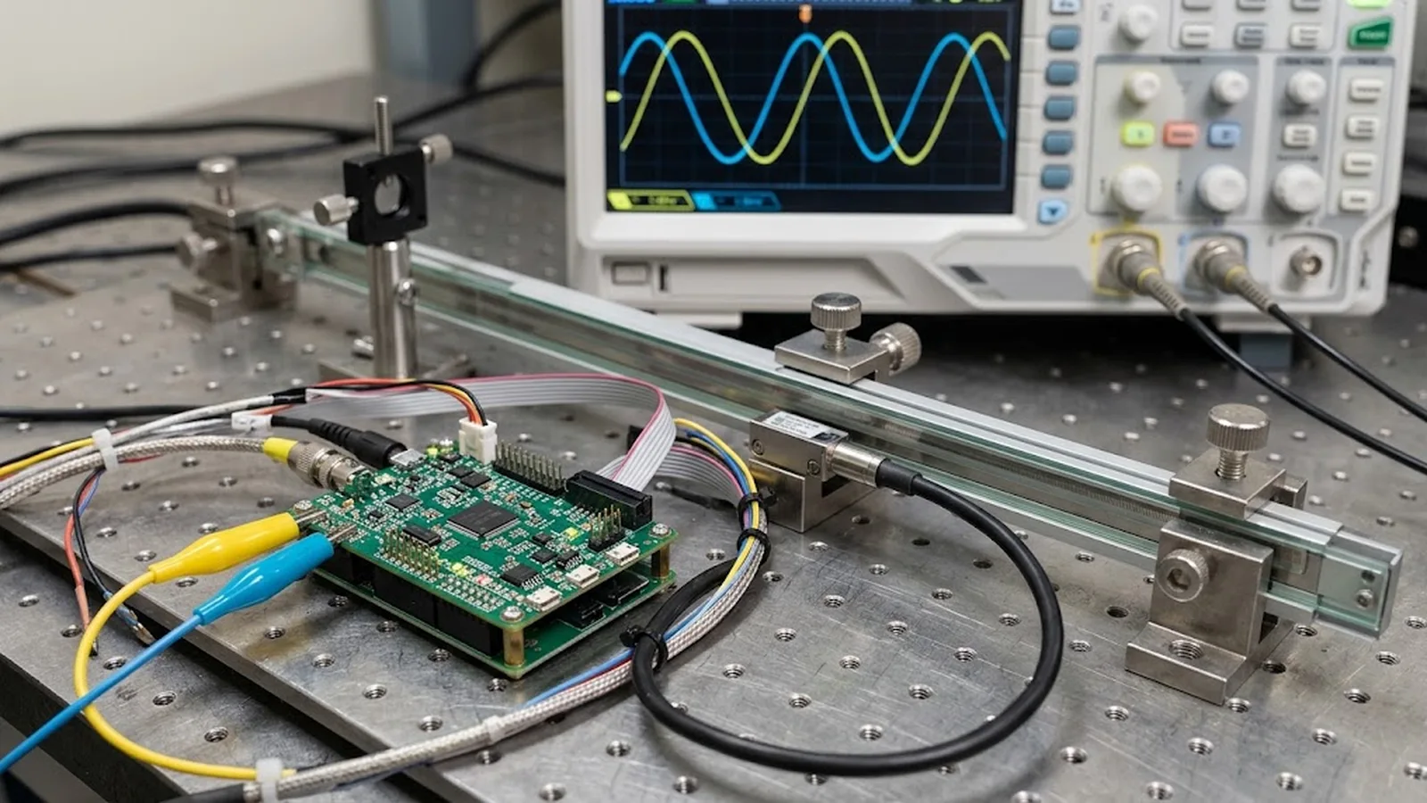
A transmitted-light optical readhead illuminates a periodic scale grating and detects the resulting light modulation with photodiodes arranged to produce two signals 90 degrees apart: sine and cosine. Over one scale pitch, the pair completes one full cycle. The 90-degree shift is what makes fine position recoverable, because it turns the pair into a two-dimensional coordinate. Plotting cosine against sine traces a circle, and every position within the pitch corresponds to exactly one angle on that circle.
Direction and coarse travel come free from the same pair. As the readhead moves forward the point rotates one way; reversed motion rotates it back. The controller can count full periods for coarse position while the angle within the period supplies the fine position. This dual role is why the sine/cosine pair remains the backbone of incremental optical encoding even as electronics have pushed subdivision factors from tens to tens of thousands.
Subdivision is the measurement of the phase angle within the sine/cosine cycle. The electronics compute the angle, typically through an arctangent function or equivalent analog phase method, and divide the full 360 degrees of the cycle into equal steps. A subdivision factor of 4096 on a 20 µm pitch yields a theoretical increment of about 4.9 nm. The published resolution is simply pitch divided by the subdivision factor, rounded to the output format the interface transmits.
The angle computation is only as good as the signals feeding it. The arctangent assumes a circle: equal amplitudes, zero DC offset, no harmonic distortion and correct 90-degree phasing. Each violation deforms the circle into an ellipse or off-center spiral, and the deformation returns as a periodic position error that repeats once or twice per pitch. This is why interpolated resolution is quoted from a clean bench signal, and why installation, gain setup and contamination control determine whether the machine achieves anything close to it.
Signal quality sets the practical ceiling. Noise on the sine and cosine inputs translates through the angle computation into position jitter, so the signal-to-noise ratio bounds how finely the period can be divided before the extra digits report noise rather than position. Amplitude imbalance between channels, DC offsets and residual harmonics each contribute systematic periodic error components with distinct signatures, which is why interpolation error testing measures the error over one pitch and compares it against the signal parameters.
Speed and bandwidth impose a second ceiling. At maximum velocity the signal frequency equals velocity divided by pitch, and the electronics must sample, compute and transmit position within the control-loop period. Higher subdivision means more computation per period and finer output timing requirements. This is where pitch selection interacts with interpolation: a coarser pitch lowers the signal frequency at speed and buys bandwidth headroom, while a fine pitch raises signal frequency and demands faster electronics for the same velocity.
Start the selection from the error budget, not the finest number on the datasheet. Ask what position uncertainty the process tolerates, then allocate shares to scale accuracy, interpolation error, mechanics, thermal behavior and environment. An interpolated resolution several times finer than the sum of the other error sources contributes little except cost and bandwidth pressure; conversely, resolution coarser than the servo loop can use wastes control performance. The right setting is the one that keeps the output increment below what the loop can correct, with interpolation error small against the budget.
For specification and purchase, require the configuration-specific data: subdivision factor, interpolated resolution, maximum output frequency for that setting, the signal amplitude window and the interpolation error figure over one pitch. Confirm that the gain and offset setup procedure is defined for installation, because a subdividing interpolator commissioned by signal level rather than by guesswork keeps its periodic error specification in service. SENFU documents resolution options and signal behavior per configuration, and the application review can map them to your travel, speed, controller and environment before order.
CONCLUSION
Sine/cosine interpolation is the mechanism that lets an optical encoder report position far below its scale pitch: two quadrature signals trace a circle, and the electronics subdivide the angle around it. The same mechanism ties resolution to signal integrity, because every imbalance, offset and distortion of the signals returns as periodic position error at the machine.
Treat interpolated resolution as a configuration choice to be justified by the error budget, speed profile and controller bandwidth, and verify it with interpolation error data and a documented signal setup. Then the fine numbers on the datasheet become numbers the machine actually delivers.
SOLUTION ROUTES
EVIDENCE CHECKLIST
FAQ
Sine and cosine shifted 90 degrees form a two-dimensional coordinate: plotting them against each other traces a circle whose angle uniquely encodes position within each scale period. One signal alone cannot distinguish direction or position within a period; the pair supports both coarse counting and fine phase interpolation.
Divide the scale pitch by the subdivision factor. For example, a 20 µm pitch with a 4096-fold subdivision gives a theoretical increment near 4.9 nm, subject to the output format and the actual interpolation error.
No. It improves resolution, meaning finer reported increments. Accuracy depends on scale error, interpolation error, installation, thermal behavior and calibration. If signals are degraded, a higher subdivision factor can even report noise as position.
Amplitude imbalance between sine and cosine, DC offsets, harmonic distortion and phase error away from 90 degrees. Each deforms the signal circle and reappears as a periodic error repeating once or twice per scale pitch, which interpolation error testing can identify.
Signal frequency equals velocity divided by pitch. A fine pitch raises frequency at a given speed, consuming electronics bandwidth and limiting usable subdivision; a coarser pitch leaves headroom, which is why high-speed axes often use coarser-pitch scales with high-speed interpolation architectures.
AUTHORITATIVE SOURCES
TECHNICAL REVIEW
Send the application, critical parameters and any drawing or process information available.
Discuss your application ↗