
XY-mode observation capability
Access to the raw analog or diagnostic sine and cosine channels and an oscilloscope or analyzer able to plot one against the other in XY mode.
TECHNOLOGY / ENCODER SIGNAL TUNING
The Lissajous ellipse of an encoder's sine and cosine channels is the fastest diagnostic in precision motion: it shows amplitude balance, phase quadrature error, DC offset and distortion in one glance. This guide explains how to read the figure, what each defect looks like, and how to tune a readhead against it.
Published
DIRECT ANSWER
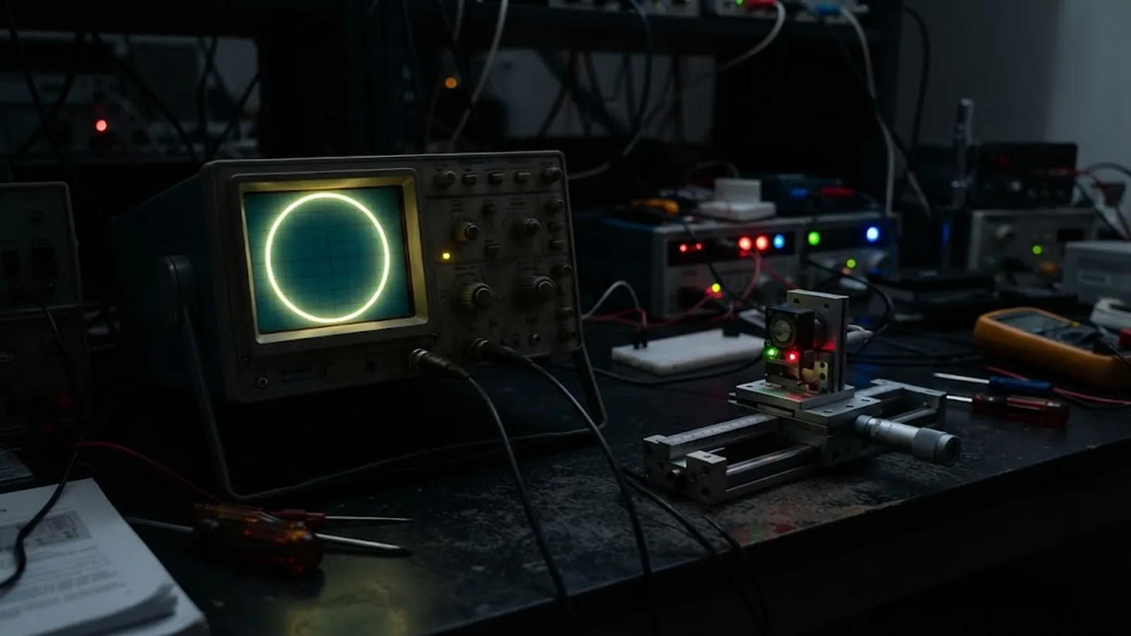
Plotting the sine channel of a quadrature encoder against the cosine channel on an oscilloscope in XY mode produces a Lissajous figure: for a healthy encoder, a clean circle centred on the origin. Every common signal defect distorts that circle in a characteristic way—amplitude mismatch flattens it into an ellipse tilted along an axis, DC offset displaces it from the origin, phase error away from 90 degrees turns it into an oblique ellipse, and harmonic distortion gives it thickened or lobed sides. Because the figure integrates all of these error sources into a single image, it is the most information-dense check available on a readhead.
Tuning uses the same geometry. After mechanical alignment is final, gain, offset and phase are adjusted until the figure becomes as close to a circle of correct radius as the hardware allows. The interpolation electronics assume exactly this ideal circle; every departure from circularity is a periodic position error at the signal period, so a round Lissajous figure is a direct visual guarantee of low sub-divisional error.
ENGINEERING CONTEXT
Quadrature encoders are usually accepted on the strength of a motion check: the axis counts, moves both directions, repeatability looks fine on the DRO. But interpolation quality depends on the relationship between the two analog channels—equal amplitudes, exact 90-degree phase, zero offset—and small departures produce periodic position ripple within every signal period, worst at low speeds where the servo cannot average it out. Checking these parameters one at a time with time-domain scopes is slow and easy to get wrong. Teams that skip the check inherit sub-divisional error of unknown origin, and when it is finally measured, nobody can tell whether amplitude, phase or offset is the culprit.
Discuss your requirement ↗CRITICAL REQUIREMENTS
Access to the raw analog or diagnostic sine and cosine channels and an oscilloscope or analyzer able to plot one against the other in XY mode.
A readhead or signal conditioning stage with per-channel gain and offset adjustment, and phase correction—either electronic or via fine mechanical tilt of the reading window.
Scale alignment, gap and mounting finished and torqued, since the electronic trim can only compensate residual electrical imbalance, not bad installation.
A stated tolerance for the figure's roundness and radius—matched to the encoder's sub-divisional error specification—so the tune is signed off against a number, not an impression.
BUYER MATRIX
Give every shortlisted supplier the same process definition and request configuration-specific proof.
| Figure appearance | Signal cause | Position error signature | Remedy |
|---|---|---|---|
| Ellipse wide along one axis | Amplitude imbalance between sine and cosine | Periodic ripple at signal period and harmonics | Trim per-channel gain to equalize |
| Circle displaced from origin | DC offset on one or both channels | Second-harmonic ripple, asymmetric counts near thresholds | Null offsets with the axis stopped at signal midpoints |
| Oblique ellipse, axes not aligned to screen | Phase error away from 90 degrees | Interpolation gain varies through the cycle; ripple at signal period | Phase trimming network or fine tilt of the reading window |
| Thick or lobed trace sides | Harmonic distortion from clipping or optics | Sub-divisional error spikes at specific phase angles | Reduce gain to avoid saturation; check gap, contamination, LED drive |
| Noisy, fuzzy boundary | Noise, EMC pickup or poor grounding | Position jitter, worse at low speed | Shielding and grounding fixes before any gain trim |
Interpolation electronics treat the sine and cosine channels as coordinates of a point rotating around a circle: position is derived from the angle of that point, arctangent-style. The mathematics assumes the ideal case—equal amplitudes, exactly 90 degrees apart, zero DC offset, undistorted sinusoids. Under that assumption the locus of the point is a perfect circle, and angle maps linearly onto position within the signal period. Every real-world defect bends the locus away from the circle, and each bend maps directly to a periodic position error.
This one-to-one correspondence is what makes the Lissajous figure more than a novelty. Amplitude imbalance squashes the circle along one axis; the arctangent of unequal coordinates is no longer linear in position, producing ripple at the signal period. A DC offset shifts the circle off the origin and injects a second-harmonic component. Phase error away from quadrature rotates the ellipse diagonally and makes the interpolated gain vary through the cycle. Harmonic distortion adds lobes and thickened regions at specific phase angles. Reading the figure, an experienced eye can name the defect, and often its channel, in seconds.
Begin with mechanics, because the electronics can only trim residual electrical error. Finalize scale alignment, gap and mounting torque; a mechanically tilted reading window shows up as a phase error that no potentiometer should be asked to hide. Then, with the axis either stopped at a signal midpoint or moving at slow constant velocity, display sine on the X input and cosine on the Y input. Establish the baseline figure and identify the dominant defect from the table of signatures.
Tune in a fixed order: offsets first, with the axis stopped so the trace sits as a dot—null each channel at its midpoint; then gain, equalizing amplitudes so the figure's extents are symmetric; then phase, using the readhead's phase trim or, where none exists, verifying that residual phase error is within the datasheet allowance. Finish by checking roundness against the target: a figure that is round and correctly sized over the full stroke guarantees that the interpolation electronics receive the signals they were designed for.
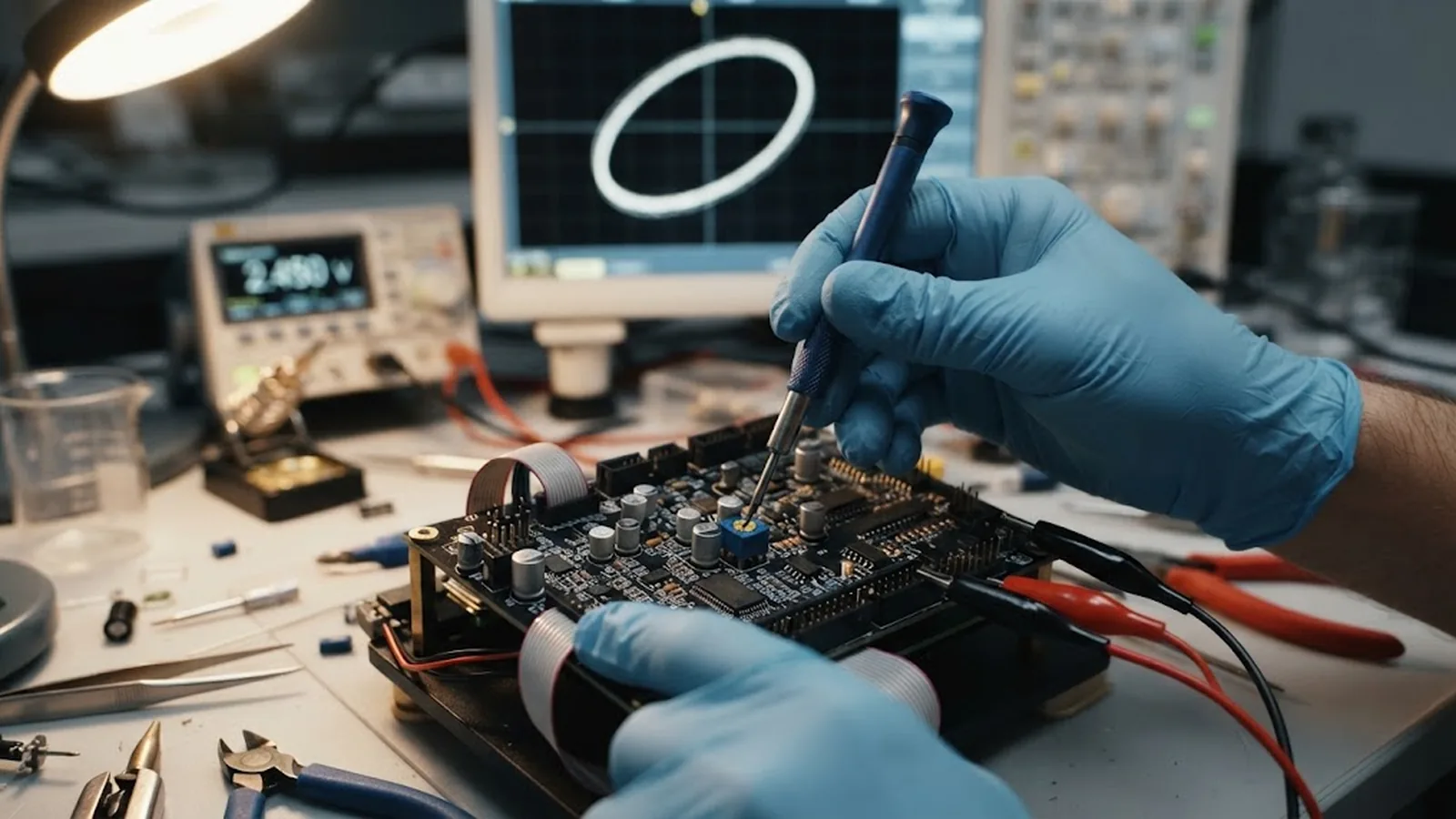
The Lissajous figure is a diagnostic and a tuning aid, but acceptance should close on numbers. Radial deviation from the best-fit circle—often called electrical circularity—is the quantity that predicts sub-divisional error: interpolation error is bounded by the deviation of the locus from the ideal circle, scaled by the signal period. Capturing the figure after tuning and reporting amplitude ratio in percent, offsets as a fraction of amplitude, phase deviation in electrical degrees, and circularity as a percentage gives the commissioning record a numerical anchor.
The final verification is a measured sub-divisional error trace, from a reference instrument or the encoder's own diagnostic output if provided, confirming that the visually round figure delivers the specified periodic error. This two-step—tune by eye, accept by number—keeps the procedure fast without leaving the result to judgement.
The figure that is round at commissioning does not stay round by itself. LED aging reduces both amplitudes, but rarely equally, so imbalance creeps in; contamination films attenuate light non-uniformly across the reading window, introducing both offset and distortion; thermal cycling moves gap and window alignment, shifting phase. Periodic re-capture of the figure on service intervals, compared against the commissioning capture, exposes all of these long before counting behavior degrades.
Where the encoder provides internal diagnostics—signal level, AGC state, quadrature warning flags—those parameters should be wired into monitoring, with the Lissajous capture reserved for commissioning and deep diagnostics. The combination gives both continuous supervision and a physical, interpretable picture when something drifts.
CONCLUSION
The Lissajous figure is the encoder's own statement of health: amplitude balance, quadrature phase, DC offset and distortion rendered as geometry. A round, correctly sized circle is the visual precondition for low sub-divisional error, and each characteristic deformation points to its own cause and remedy.
Tune offsets, gain and phase in that order after mechanics are final, accept the result with measured circularity and sub-divisional error numbers, and re-capture the figure on service intervals. The five minutes it takes is the cheapest insurance available on interpolation quality.
EVIDENCE CHECKLIST
FAQ
The sine channel plotted against the cosine channel in XY mode. A healthy quadrature pair produces a circle centred on the origin; amplitude imbalance, DC offset, phase error and harmonic distortion each deform the circle in a characteristic, diagnosable way.
Interpolation derives position from the angle of the sine-cosine point, assuming a circular locus of equal amplitude, 90-degree-shifted, offset-free sinusoids. Any departure from the circle makes the angle-to-position mapping nonlinear, which appears as periodic error within each signal period.
Offsets first, with the axis stopped so each channel can be nulled at its midpoint; then per-channel gain to equalize amplitudes; then phase, electronically or by fine tilt of the reading window. Adjusting phase before offsets leaves residual distortion that the later trims will move again.
The radial deviation of the Lissajous locus from its best-fit circle, usually expressed as a percentage of amplitude. It directly bounds the interpolation error the electronics will produce, so it is the natural acceptance number for a quadrature tune.
No. The figure is a fast diagnostic and tuning guide; acceptance should still include a measured sub-divisional error trace from a reference instrument or diagnostic output. The two together—tune by eye, accept by number—are fast and objective.
AUTHORITATIVE SOURCES
TECHNICAL REVIEW
Send the application, critical parameters and any drawing or process information available.
Discuss your application ↗