
Motor electrical data on hand
Pole-pair count, electrical cycle definition, and the drive's expected sector table are needed to convert measured signal timing into electrical-degree error; without them, scope traces cannot be judged.
TECHNOLOGY / OPTICAL ENCODER
UVW commutation tracks tell a brushless drive where the rotor is within each electrical cycle, and their alignment to the ABZ incremental signals decides whether the motor runs smoothly or ripples. This guide explains the UVW-to-ABZ relationship, how commutation angle error becomes torque ripple, a practical oscilloscope alignment procedure, and how factory calibration is verified in the field.
Published
DIRECT ANSWER
UVW commutation channels are three additional tracks on an incremental optical encoder that repeat once per electrical cycle of the motor—one full period every 360°/pole-pairs of mechanical rotation—offset 120 electrical degrees from each other. They give the drive a coarse absolute rotor angle so it can energize the correct phase pair at power-up, before the high-resolution ABZ incremental signals take over for position and velocity. Alignment means the UVW edges sit at defined ABZ positions: when the U channel rising edge occurs, the A/B states must match the sector table the drive expects, within a few electrical degrees.
Commutation angle error converts directly into torque ripple and lost average torque: roughly the sine of the electrical error appears as ripple, so ten degrees of misalignment is consistent with fifteen to twenty percent ripple in block-commutated systems, felt at low speed as cogging, heard as acoustic noise, and seen as speed jitter that servo tuning cannot remove. The cure is procedural: verify the UVW-to-ABZ phase relation with a two-channel oscilloscope against the six-sector truth table, confirm quadrature quality, and document the commutation offset at factory calibration so field verification has a baseline to compare against.
ENGINEERING CONTEXT
A brushless motor that runs rough at low speed, hums under load, or refuses to start smoothly is often blamed on the drive, the tuning, or the mechanics—when the actual culprit is a commutation signal misaligned by a few electrical degrees. Because UVW channels are coarse by design, a system can appear fully functional: the encoder counts correctly, the index fires, the servo loops hold position. Only the conversion between encoder phase and stator phase is wrong, and it announces itself as ripple, noise, and efficiency loss rather than as an error code. Integration teams assembling third-party motors with third-party encoders inherit the risk directly, since alignment is established at encoder manufacture and finalized in the drive. Without a documented alignment procedure and a recorded factory offset, every motor swap or encoder replacement re-opens the question with no baseline to compare against.
Discuss your requirement ↗CRITICAL REQUIREMENTS
Pole-pair count, electrical cycle definition, and the drive's expected sector table are needed to convert measured signal timing into electrical-degree error; without them, scope traces cannot be judged.
UVW and AB outputs are differential signals; probing them single-ended with shared grounds corrupts edges. A 100 MHz-class scope with differential probes or proper differential-to-single-ended adapters is the working minimum.
Alignment checks need repeatable shaft angles—hand rotation for static edge checks, a low-speed torque-mode spin for back-EMF comparison, or a second drive motor as a rotator.
The baseline for field verification is the as-shipped alignment: the encoder manufacturer's mechanical UVW preparation and any drive-side electrical offset recorded at commissioning.
BUYER MATRIX
Give every shortlisted supplier the same process definition and request configuration-specific proof.
| Aspect | Static six-sector check (scope) | Back-EMF comparison (scope) | Drive auto-calibration (locked rotor) |
|---|---|---|---|
| What it verifies | UVW-to-ABZ phase relation against the sector table | UVW phase against the motor's own back-EMF | Electrical zero at the drive, given working UVW or ABZ |
| Equipment | Oscilloscope, differential probes, hand rotation | Oscilloscope plus a rotation source, motor leads accessible | The commissioning drive only |
| Detects | Encoder-side alignment errors, sector logic mismatch | Encoder-to-motor electrical angle error including stator placement | Drive-side offset; assumes encoder hardware is correct |
| Best use | Incoming inspection and field verification | First-time integration of motor and encoder | Final commissioning step after the above two pass |
An incremental optical encoder with commutation outputs carries two independent signal families on the same code disc. The ABZ family is the metrology: A and B are quadrature square waves repeating every mechanical line pitch, and their count gives position with the encoder's full resolution; Z fires once per revolution to define the datum. The UVW family is the motor's coarse clock: three channels spaced 120 electrical degrees apart, each completing one full period per electrical cycle of the motor—that is, every 360°/pole-pairs of mechanical rotation. On a ten-pole-pair motor, the U channel repeats every 36 mechanical degrees, and the drive only needs to know the rotor angle within one sector (±30 electrical degrees) to apply current to the correct phase pair at power-up.
The two families are physically linked: UVW tracks are exposed or masked on the same disc and read by the same optics, so their phase relation to ABZ is fixed at manufacture. When the encoder is correctly aligned, every UVW edge transition lands at a defined ABZ state—count N after the index, A high and B low, and so on, six sectors per electrical cycle. Alignment quality is exactly this: how closely the measured UVW edges match the expected ABZ positions, expressed in electrical degrees. A drive that trusts misaligned UVW channels applies its phase current at the wrong stator angle, and no amount of downstream servo gain fixes the error at the source. The incremental tracks and their own failure modes are covered signal by signal in the ABZ troubleshooting guide, which pairs naturally with this alignment check.
A brushless drive produces smooth torque only when the stator current vector leads the rotor's electrical angle correctly. Commutation angle error shifts that vector: in sinusoidal commutation the average torque falls with the cosine of the error while the current between phases no longer converts cleanly into rotation, and in block or six-step commutation the error appears directly as ripple at the electrical frequency and its harmonics. As a working rule, the dominant ripple grows roughly with the sine of the electrical error—five degrees of misalignment is consistent with around nine percent ripple, ten degrees with fifteen to twenty percent, and a worst-case hall-style sector error of thirty electrical degrees can waste half the torque capacity at some rotor positions. The error also shows up as phase-current imbalance, extra heating, and acoustic noise with a signature tied to speed: ripple frequency scales with rotation, which is how it is distinguished from bearing or mechanical defects.
For precision stages the consequences compound. Low-speed jitter from torque ripple limits velocity stability exactly where scanning and metrology applications operate, and it forces the servo loops to be detuned to avoid amplifying the disturbance. Position loops then hunt around the command, encoder interpolation sees irregular motion, and throughput drops because smooth slow moves become impossible. Keeping the total commutation chain—encoder mechanical alignment plus drive electrical offset—inside about ±5 electrical degrees is a reasonable target for demanding motion systems, and the budget should be written into the integration specification rather than discovered at commissioning. How ripple and residual periodic error propagate into servo behavior is treated in the encoder feedback tuning guide, which covers the loop side of the same budget.
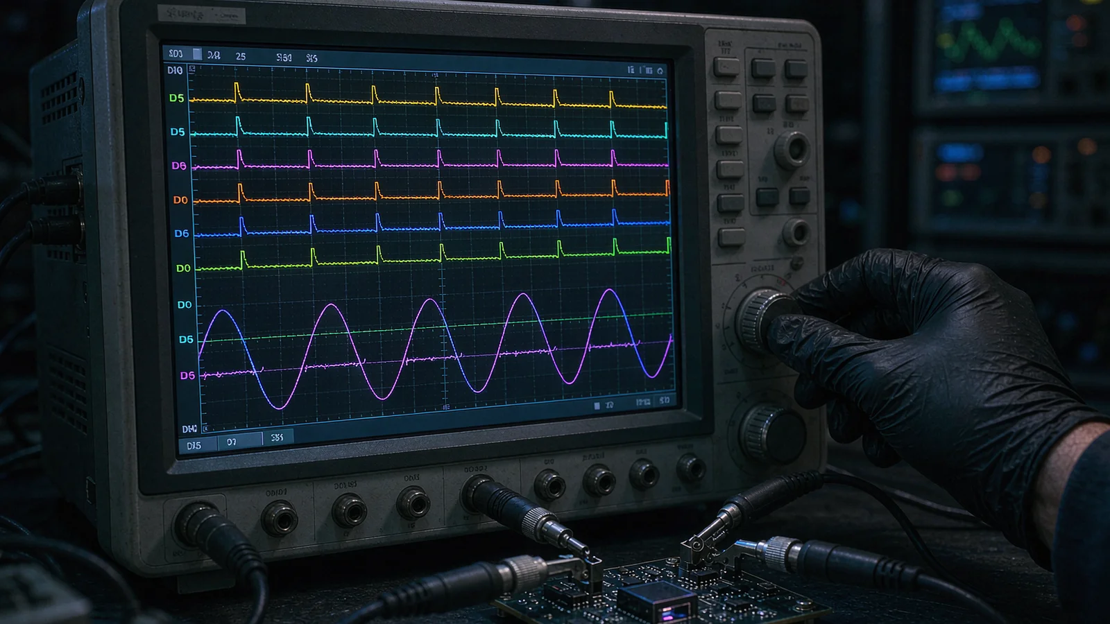
Preparation first. Power the encoder from a current-limited supply at its rated voltage and terminate the differential outputs per the datasheet; probe U, V, W, A and B with differential probes or a proper differential front end, keeping grounds clean. Use a 100 MHz-class scope, trigger on the U rising edge, and rotate the shaft slowly and repeatably—by hand for static checks, or with the drive in torque mode at a few RPM with the phase leads disconnected from power for dynamic checks.
Method one is the static six-sector check. Rotate the shaft until the U channel rises, freeze the display, and record the A and B logic states and the AB counter reading. Advance through one full electrical cycle and repeat at every UVW edge: six transitions, each with an expected AB state from the drive's sector table. Convert any mismatch into angle directly—each AB count is 360/(counts per revolution) mechanical degrees, multiplied by the pole-pair count to give electrical degrees. The same pass yields the quality checks: UVW duty cycles near fifty percent, edge spacing near 120 electrical degrees, and clean edges with no chatter at the thresholds.
Method two is the back-EMF comparison, the definitive check of encoder-to-motor electrical angle. Spin the motor with an unpowered drive or a second rotator and scope one phase back-EMF against the U channel: for the standard 120-degree sensor placement, the U rising edge should coincide with the phase back-EMF zero crossing. Repeat for the V and W phases against their own EMFs. Any fixed offset here is the commutation angle error; small residuals can be entered into the drive's commutation offset register, but a large or speed-dependent error points at encoder mounting or stator placement and must be fixed mechanically. Quadrature quality of the A and B channels themselves—phase error and amplitude balance—should be verified in the same session using the Lissajous method described in the quadrature signal tuning guide.
Alignment is established in two stages that must not be confused. At the encoder manufacturer, the UVW mask and code disc are positioned and verified against the ABZ tracks—often with optical datum equipment—and the resulting commutation relation is checked over temperature and recorded with the unit. At the motor or stage integrator, the drive-side electrical zero is finalized: the classic procedure locks the rotor with a known current vector, reads back the encoder position, and writes the commutation offset register. Both numbers together define the delivered alignment, and both belong in the shipment documentation—an unrecorded offset is a baseline lost, and the incoming acceptance test should specifically check that commutation data accompanies the encoder.
Field verification repeats the factory evidence rather than re-deriving it. After any motor swap, encoder replacement, or coupling rework, run the static six-sector check and compare the electrical-degree error against the as-shipped record; then spin at low speed with a clamp-on current probe and compare phase-current ripple against the commissioning baseline. The drive offset register can absorb a few electrical degrees of drift, but it should be treated as a trim, not a repair: a result that differs materially from the factory record means something mechanical moved, and reseating the encoder or correcting the mounting beats compensating for it. Systems built this way—documented factory alignment, sector-table verification on receipt, and ripple comparison after every intervention—keep commutation quality a specification instead of a surprise, which is the operating assumption in precision motion applications where torque ripple is a measured line item.
CONCLUSION
UVW commutation tracks and ABZ incremental signals come from the same code disc but serve different masters: the drive's need for a coarse absolute rotor angle and the servo's need for fine position. Their fixed phase relationship is what converts encoder counts into correctly timed phase currents, and any deviation appears as torque ripple that grows roughly with the sine of the electrical error.
The working discipline is short and repeatable: know the pole-pair count and sector table, verify the six UVW-to-ABZ transitions with a scope, confirm the back-EMF relation before trusting drive-side offsets, and keep the factory-committed alignment on record so field checks compare against evidence instead of memory. Treated as a calibration with a baseline, commutation alignment stays within the few electrical degrees that smooth, quiet, efficient motion requires.
EVIDENCE CHECKLIST
FAQ
They are separate tracks on the same code disc. ABZ provides high-resolution quadrature position (A, B in 90-degree phase) plus one index pulse Z per revolution. UVW provides three commutation channels spaced 120 electrical degrees apart, repeating once per electrical cycle (360°/pole-pairs of mechanical rotation). When aligned, each UVW edge occurs at a defined ABZ state, and that relationship is what the drive's sector table assumes.
For demanding motion systems, hold the total chain—encoder mechanical alignment plus drive electrical offset—within about ±5 electrical degrees. Ripple grows roughly with the sine of the error, so five degrees corresponds to roughly nine percent ripple, ten degrees to fifteen to twenty percent. Generic industrial drives with hall-style sensors tolerate up to ±30 electrical degrees because sector resolution is coarse, but precision stages should not plan on that allowance.
Only within limits. The register trims a few electrical degrees of residual error and records the electrical zero at commissioning. A large error—UVW edges landing in the wrong sectors, or an offset that varies with speed—indicates mechanical misalignment of the encoder or a sector-table mismatch, which should be corrected physically rather than compensated, since compensation hides the root cause and consumes alignment margin.
The ripple is periodic with the electrical cycle, so its frequency scales with rotation speed. At low speed the ripple falls within the servo loop's bandwidth and inside human hearing, appearing as speed jitter, cogging, and acoustic noise; at high speed it moves above the loop bandwidth and averages out in the velocity estimate. Low-speed operation is therefore both the symptom location and the standard test condition for verification.
Repeat the static six-sector check—AB state and count at all six UVW transitions per electrical cycle—and compare the computed electrical-degree error against the factory record. Then run a low-speed spin with a current probe and compare phase-current ripple to the commissioning baseline. Re-enter the drive commutation offset only if the mechanical result matches the record; a deviation means reseat and remeasure before compensation.
AUTHORITATIVE SOURCES
TECHNICAL REVIEW
Send the application, critical parameters and any drawing or process information available.
Discuss your application ↗