
Runout budget at the scale radius
Convert the angle error budget into micrometres of allowable radial and axial runout at the effective scale radius, and specify the bearing grade against that number.
TECHNOLOGY / ANGULAR FEEDBACK
On a rotary axis the bearing is part of the measurement chain: radial and axial runout become encoder harmonics, and structural vibration becomes jitter and count errors. This guide connects bearing choice to angular encoder performance and lists the evidence a rotary-axis specification should demand.
Published
DIRECT ANSWER
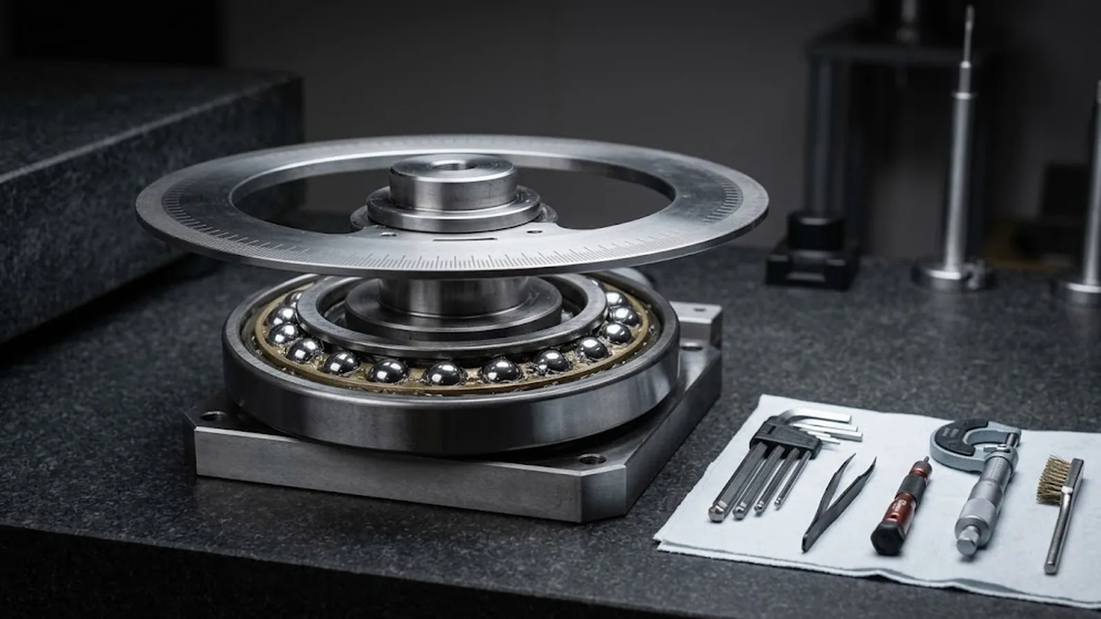
An angular encoder measures the angle between its scale, usually mounted on the rotor, and its readhead, usually mounted on the stator. Everything that moves one relative to the other except true rotation enters the measurement. Bearing radial runout and axial float therefore appear as once-per-revolution and higher harmonic errors; ball pass vibration modulates the readhead gap and adds velocity ripple and jitter; resonance in the bearing structure amplifies count errors at specific speeds. The encoder datasheet cannot remove these terms because they are created after the scale.
Select the bearing as a metrology component. Match the runout grade to the angle error budget converted through the effective scale radius, require preloaded, stiff bearing arrangements for readhead gap stability, and verify the assembled axis rather than the parts: measure angle error against a reference over full revolutions, record the harmonic signature, and check jitter across the speed range. Where the budget is tight, error mapping compensation can remove repeatable runout harmonics, but only after the bearing and its mounting have made them repeatable in the first place.
ENGINEERING CONTEXT
Rotary axis accuracy problems are persistently misattributed because the encoder and the bearing are purchased from different suppliers, specified in different documents and installed by different hands. The bearing datasheet speaks of load ratings and stiffness; the encoder datasheet speaks of arc-seconds and interpolation. Nobody owns the coupling between them, which is precisely where large rotary applications lose their accuracy: a runout of a few micrometres reads as seconds of arc on a mid-sized ring, ball-pass vibration unsettles the interpolation at speed, and a resonant bracket turns a smooth axis into one that drops counts in a narrow speed band. Demonstration at low speed in the middle of the range conceals all three. The remedy is to make the coupling contractual: convert the angle budget into an allowable runout at the scale radius, specify preload and gap stability, and require assembled-axis evidence, harmonic analysis and speed-sweep jitter, as acceptance conditions.
Discuss your requirement ↗CRITICAL REQUIREMENTS
Convert the angle error budget into micrometres of allowable radial and axial runout at the effective scale radius, and specify the bearing grade against that number.
Require a defined preload condition and stiffness figures so readhead gap and tangent behaviour stay stable across load, orientation and temperature.
Demand angle error measurement over full revolutions plus a jitter and velocity-ripple check across the operating speed range, not component-level datasheets alone.
Review the readhead bracket, ring scale mounting interface and natural frequencies against the ball-pass and motor excitation frequencies of the application.
BUYER MATRIX
Give every shortlisted supplier the same process definition and request configuration-specific proof.
| Mechanism | Origin in the bearing system | Feedback signature | Mitigation to specify |
|---|---|---|---|
| Radial runout | Radial bearing eccentricity and raceway imperfections between rotor and stator | Once-per-revolution and low harmonic angle error, largest for small scale radii | Higher bearing grade selected from the runout budget at scale radius, optional error mapping |
| Axial float and tilt | Axial play or wobble under load reversal | Gap modulation that shifts amplitude, and cosine errors between adjacent readheads | Preloaded bearing arrangement with stiffness matched to the working loads |
| Ball-pass vibration | Rolling elements passing raceway defects at characteristic frequencies | Jitter and velocity ripple at specific speeds that vanish at others | Raceway quality specification, preload verification and a speed-sweep jitter test |
| Structural resonance | Bracket or housing natural frequency excited by ball-pass or motor forcing | Count errors and noise spikes in a narrow, repeatable speed band | Stiff bracket design, damping and resonance review against excitation frequencies |
| Thermal growth | Bearing and housing expansion shifting the rotor-stator centre and gap | Slow amplitude and offset drift correlated with warm-up rather than position | Symmetric mounting geometry, materials with matched expansion and warm-up procedure |
| Mounting stress | Clamping forces distorting a thin ring scale or the bearing races | Angle error that repeats with rotation but changes after each re-assembly | Controlled clamping sequence, datum faces and re-verification after any disassembly |
An angular encoder reports the relative angle between scale and readhead, and on a conventional rotary stage the only thing that should ever change that angle is commanded rotation. The bearing is the mechanical promise that this is true. Every micrometre of radial runout shifts the rotor laterally relative to the stator, every micrometre of axial float changes the readhead gap, and both appear in the feedback as angle terms the encoder cannot distinguish from real rotation. The datasheet accuracy of the scale is therefore a ceiling the assembled axis approaches, never a guarantee it inherits.
The conversion is brutally geometric. Angle error in radians equals radial displacement divided by the effective radius at which the scale measures, so a five-micrometre runout on a fifty-millimetre radius is already one hundred microradians, twenty arc-seconds, while the same runout on a two-hundred-millimetre ring is five arc-seconds. Small-diameter rotary modules suffer most, which is exactly where miniature bearings with relaxed runout grades are most tempting. Writing the runout budget in micrometres at the scale radius, before choosing a bearing, turns a vague accuracy hope into a selectable grade.
Runout is diagnosable from its shape. A pure centre offset between scale rotation axis and bearing axis produces a once-per-revolution sinusoid in the angle error, the classic eccentricity signature, and it repeats identically every revolution. Raceway imperfections and rolling element errors add harmonics at multiples of the revolution frequency and at ball-pass frequencies that depend on the bearing geometry and speed. Plotting angle error against angle over several revolutions, then examining the spectrum, separates static geometry from dynamic bearing behaviour in a single measurement session.
The repeatable part is treatable and the rest must be bought. A stable eccentricity signature can be mapped and compensated in the drive or controller, often recovering a large fraction of the error, and the accuracy verification protocol should record the spectrum before and after compensation. What compensation cannot fix is instability: a signature that changes with temperature, load orientation or re-assembly indicates the mounting or bearing itself is not settled, and no table will follow it. Repeatable first, compensated second, is the only order that survives a production floor.
At standstill, bearing imperfections are geometry; at speed they become excitation. Ball-pass frequencies, motor cogging and imbalance modulate the readhead gap, and the readhead's gain control chases the modulation, adding amplitude noise exactly where the interpolator is most sensitive. The visible result is position jitter, velocity ripple and, in the worst case, miscounting when the Lissajous trajectory is disturbed enough to cross its decision boundaries. Because the excitation is frequency specific, these faults appear and disappear across the speed range in narrow bands.
This is why a speed sweep belongs in acceptance testing. Sweep the axis through its full operating range while recording jitter and signal quality, and mark the bands where degradation appears; compare those bands against the calculated ball-pass and structural frequencies. Countermeasures differ by diagnosis: raceway and preload issues improve with bearing quality or preload adjustment, while a resonance band calls for bracket stiffening, damping or a speed exclusion programmed into the motion profile. The encoder supplier can usually contribute signal diagnostics, but only if the vibration evidence is measured on the assembled axis and shared.
Crossed roller bearings are the default for precision rotary stages: high stiffness, low runout in compact sections and predictable preload behaviour. Their limitations are speed and cleanliness sensitivity; grease behaviour and roller skidding at high speed can add vibration, and contamination in the raceway shows immediately in the feedback. Duplex angular contact ball bearings allow preload tuning across a wider speed range and suit faster rotary tables, but individual raceway quality varies more, so the runout budget must be checked against the actual grade, not the series name.
Air bearings remove mechanical contact and its ball-pass signature entirely, offering nanometre-level runout and the quietest possible feedback environment for metrology-grade rotary tables. The price is stiffness and infrastructure: they need clean, dry, filtered air, tolerate less overload, and shift the design burden to the structure around them. The selection logic is therefore budget-driven rather than preferential: convert the angle budget to micrometres at the radius, add the speed range and environment, and the bearing class usually chooses itself.
A good bearing in a bad mounting produces a repeatable-looking error that is neither. Thin ring scales are sensitive to clamping stress, so the ring scale mounting plan, datum faces, bolt sequence and torque discipline, decides whether the scale keeps its manufactured form after assembly. The readhead bracket deserves equal attention: a cantilevered bracket with a resonance near the ball-pass frequency converts bearing vibration into gap modulation, while a stiff, damped bracket mounted to the stator structure keeps the readhead observing rotation rather than participating in it.
Temperature couples the mounting to accuracy as well. Asymmetric bearing and housing geometry shifts the rotor centre as the axis warms, and readhead gap changes with it, so symmetric designs and materials with matched expansion keep the harmonic signature stable across the working day. After any disassembly the verification is not optional: the angle error spectrum must be re-recorded, because clamping stress and centre position are exactly the terms that re-assembly changes.
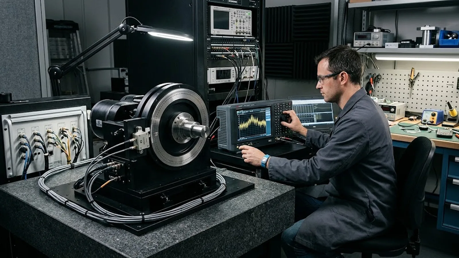
Four measurements close the loop between bearing and feedback. First, assembled-axis angle error against a reference over full revolutions, recording the harmonic spectrum, on a calibrated divider or equivalent method. Second, a speed sweep capturing jitter and velocity ripple across the operating range, with any degraded bands identified and explained. Third, amplitude and quality-index stability across a warm-up cycle, which exposes thermal centre shift and gap drift. Fourth, repeatability of the angle error spectrum after a controlled disassembly and re-assembly, which validates the mounting plan itself.
Each measurement maps to a specification clause, and together they transfer ownership of the coupling term. If the harmonics are stable, error mapping can shrink them; if jitter bands exist, they are either engineered out or excluded in the profile; if the spectrum survives re-assembly, the mounting is sound. An axis delivered with this evidence can be maintained by measurement instead of by folklore, which is the practical difference between a rotary stage that keeps its accuracy and one that is periodically rediscovered.
CONCLUSION
On a rotary axis, bearing selection and angular encoder accuracy are the same conversation: runout sets the geometric error floor at the scale radius, vibration sets the dynamic one, and the mounting decides whether either stays repeatable enough to compensate. Write the runout budget in micrometres at the radius, specify preload and resonance behaviour, and demand assembled-axis evidence at acceptance. The encoder can only report what the bearing allows it to see.
EVIDENCE CHECKLIST
FAQ
Multiply the allowed angle error in radians by the effective scale radius to get allowable radial displacement. A five arc-second budget on a fifty-millimetre radius permits roughly one micrometre of runout, which immediately constrains the bearing grade.
Frequency-specific degradation usually indicates resonance or ball-pass excitation. The bearing rolling elements and the readhead bracket interact at characteristic frequencies, disturbing gap and interpolation in bands that a speed sweep will expose precisely.
Only the repeatable part. A stable once-per-revolution signature can be mapped and compensated effectively, but a signature that drifts with temperature, load or re-assembly cannot be followed. Make the error repeatable through bearing and mounting quality first.
They offer the lowest runout and the quietest vibration environment, which suits metrology-grade tables. They require clean dry air, have lower overload tolerance and cost more structure, so for general precision axes a preloaded crossed roller or angular contact design meeting the runout budget is usually more practical.
The angle error spectrum over full revolutions, signal amplitude and quality index at the readhead gap, and the speed-sweep jitter profile. Clamping stress and rotor centre position change with re-assembly, so the previous compensation and any speed exclusions must be re-validated.
AUTHORITATIVE SOURCES
TECHNICAL REVIEW
Send the application, critical parameters and any drawing or process information available.
Discuss your application ↗