
Interface machining specification
Mounting boss or face with stated concentricity, flatness and surface finish, sized so the achievable centering runout matches the ring accuracy class.
TECHNOLOGY / ROTARY ENCODER INSTALLATION
Large-diameter ring scales turn installation quality into angle accuracy: eccentricity, axial runout, thermal mismatch and readhead alignment decide whether the datasheet accuracy survives in the machine. This guide defines the tolerances and procedures that keep a large ring on specification.
Published
DIRECT ANSWER
For a large ring scale, installation tolerance is angle accuracy. Eccentricity e between the ring's grating center and the rotation axis produces an angular error of roughly e/R radians in each direction, so 50 µm of eccentricity on a 100 mm radius ring is about 500 µrad, or 100 arcseconds—often ten times the ring's own engraved accuracy. Axial runout shifts the readhead gap around the circumference and modulates signal amplitude; both effects are visible as once-per-revolution components in the angle error.
A controlled installation therefore proceeds in fixed steps: machine the mounting interface to the stated flatness and concentricity, mount the ring by the supplier's method—bonded, clamped or elastic—center it with a dial indicator on the grating-side reference face to the specified runout, verify the readhead gap stays within tolerance over a full slow revolution, and record the runout values as the installation baseline. On diameters above a few hundred millimetres, differential thermal expansion between ring and structure must be included in the mounting design, not discovered after the first temperature cycle.
ENGINEERING CONTEXT
Ring scales behave differently from the linear encoders most machine builders are used to, and large diameters amplify every mistake. A linear scale mounted on a flat base mostly carries its own dimension; a ring mounted off-center converts each micrometre of eccentricity into angle error through the radius, and the error hides inside normal-looking signals. Centering that is easy on a 50 mm hub becomes a precision alignment task on a 400 mm ring where a few tenths of a degree of tilt changes the gap across the circumference. Thermal behavior adds a slow trap: a steel ring on an aluminium structure expands at different rates, so an installation centered at 20 °C drifts eccentric as the machine warms, and the once-per-rev error grows with nothing visibly wrong. Suppliers state eccentricity and runout tolerances, but they are frequently read as assembly suggestions rather than the accuracy-critical limits they are. The fix is to treat ring mounting as a metrology procedure with specified indicator targets, thermal-aware fixing and a recorded baseline.
Discuss your requirement ↗CRITICAL REQUIREMENTS
Mounting boss or face with stated concentricity, flatness and surface finish, sized so the achievable centering runout matches the ring accuracy class.
The supplier's prescribed mounting construction—adhesive, clamping ring or elastic mount—with torque values, adhesive type and sequence.
Numerical radial runout and axial runout limits measured with a dial indicator or probe, referenced to the rotation axis, not to the mounting spigot alone.
Readhead gap and alignment checked around the entire circumference at working speed, with amplitude variation documented as evidence.
BUYER MATRIX
Give every shortlisted supplier the same process definition and request configuration-specific proof.
| Aspect | Adhesive bonded ring | Clamped ring (screws and clamping ring) | Elastic or compliant mount |
|---|---|---|---|
| Typical diameter range | Small to medium rings where adhesive layer thickness is controlled | Medium to large rings; the standard method for bolted installation | Very large diameters and temperature-cycling environments |
| Adjustability | Adjustable before cure with fixing jig; effectively fixed after | Fine centering via slotted holes or adjustment screws, then locked | Limited adjustment; relies on interface accuracy |
| Thermal behavior | Follows substrate expansion; adhesive must be matched to the pair | Rigid fixing can build stress when ring and substrate coefficients differ | Decouples differential expansion; keeps grating stress low |
| Rework and service | Removal usually destroys the ring; plan spare and jig | Removable and re-centerable with documented procedure | Removable; compliant elements are service items |
| Main risk | Adhesive thickness variation and cure-induced stress | Over-torque distorting the ring; local stress near screw bosses | Compliance allowing slow drift if not properly preloaded |
A perfectly engraved ring still measures wrong if its grating center does not coincide with the rotation axis. With eccentricity e and ring radius R, the angle error swings approximately ±e/R radians once per revolution: on a 100 mm radius, every 10 µm of centering error contributes roughly 100 µrad, about 20 arcseconds, of systematic angular error. This term usually dwarfs the engraved accuracy of a quality ring, which is why centering is not a fitting nicety but the dominant accuracy operation of the installation.
The error is diagnosable because it is structured. In an angle-error plot against rotation, eccentricity appears as a once-per-revolution sinusoid whose amplitude gives e directly; harmonic content beyond the fundamental points to ring form error or mounting stress instead. Recording this plot at commissioning creates a baseline: if the once-per-rev term grows over the machine's life, the ring has shifted, the structure has moved or the temperature behavior was underestimated—all detectable from data before accuracy is lost.
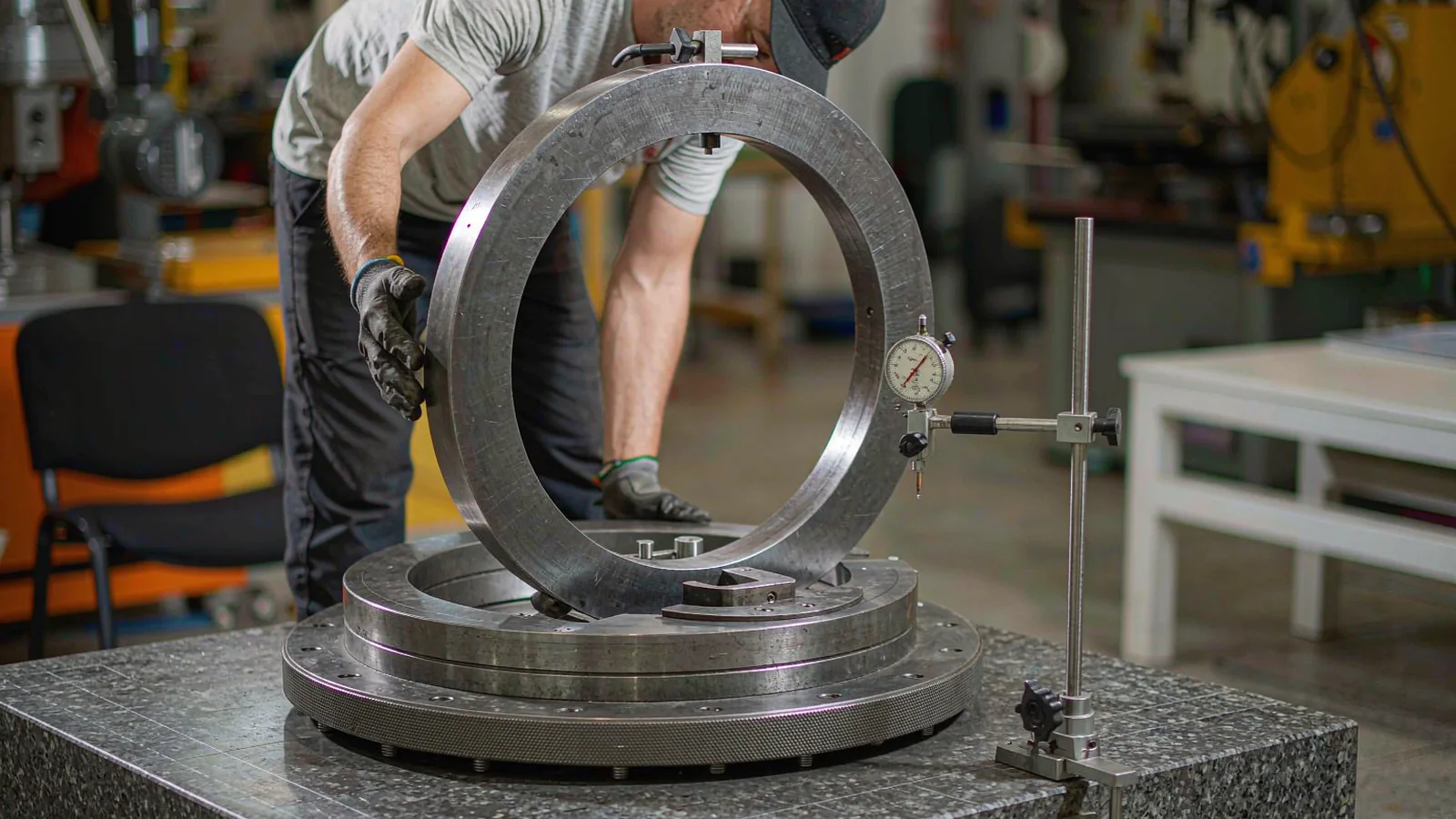
Centering compares the ring to the rotation axis, so the measurement must be taken while the axis rotates under its own bearings, not with the ring measured against a fixed spigot. Mount a dial indicator or electronic probe on a rigid arm referencing the machine structure, touch the grating-side reference face or the supplied centering surface, and record radial runout over a slow full revolution. Adjust through the ring's slotted holes or adjustment features, working in opposing pairs, and repeat until runout is within the specified limit—which for large precision rings is typically tens of micrometres, tightened further when the accuracy class demands it.
Two details decide the result. First, the indicator tip and reference face must be clean and free of burrs; a single particle lifts the reading by its own size. Second, axial runout is checked in the same session: tilt between ring and rotation plane changes the readhead gap across the circumference, and a gap that drifts from nominal to limit over one revolution modulates signal amplitude enough to threaten interpolation quality. Record both runout values with the installation report.
The fixing method must survive the temperature range, not just the assembly bench. A steel ring rigidly bolted to an aluminium structure builds differential stress with every kelvin: the mismatch bends or stresses the grating, shifts centering and can push the readhead gap across its window as temperatures change. Clamped installations manage this with defined torque and stress-relief features; bonded installations rely on a matched adhesive layer and disciplined cure; large or thermally active structures benefit from elastic mounts that carry the ring radially while absorbing differential expansion.
For multi-metre diameters, segmented or multi-head configurations replace the single ring, and the mounting plan extends to segment joints and head phasing. Whichever construction applies, the principle is the same: the ring must reach working temperature stress-free, and the mounting must hold centering across the whole specified temperature range, not only at the temperature at which it was aligned.
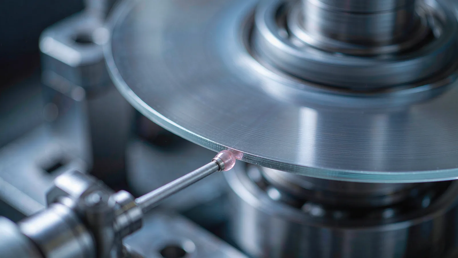
The readhead completes the installation. Set nominal gap and both angular alignments to the datasheet values, then verify over a full slow revolution that the gap and signal amplitude stay inside tolerance around the whole circumference—axial runout, edge burrs and interface steps all show up here. Check signal quality as-installed: amplitude, index mark strength and, where available, interpolation error indication. A head aligned to spec on a poorly mounted ring still produces marginal signals, so amplitude variation around the revolution is the fastest combined verdict on ring and head together.
Close the installation with documented evidence: runout values, gap measurements, signal amplitudes at defined positions and an angular accuracy verification against the agreed protocol. This evidence set is what allows a later accuracy drift to be attributed—to ring shift, structural movement or readhead wear—rather than debated. It also becomes the acceptance record for the purchase, the same discipline used for the machine's linear axes.
SENFU supplies angular encoder rings with explicit centering runout limits, gap specifications and recommended fixing constructions for each diameter class, so the mounting interface can be designed before the mechanics are frozen. When a rotary axis requirement is submitted with diameter, accuracy class, temperature range and structure material, SENFU can propose the mounting method and the tolerances the interface drawing must carry.
For large diameters and demanding accuracy classes, SENFU can also support the centering and verification work on site or through partners, from indicator procedure to the angular accuracy measurement that closes the acceptance record.
CONCLUSION
On large-diameter ring scales, installation tolerance and angle accuracy are the same subject. Eccentricity converts directly into angular error through the radius, axial runout modulates the readhead gap around the circumference, and thermal mismatch between ring and structure moves both slowly over the machine's life. Treating centering as a metrology procedure—indicator targets, supplier fixing method, gap verification over a full revolution—keeps the datasheet accuracy alive in the machine.
Record the runout values, signal amplitudes and the commissioning angle-error plot as the installation baseline. With that evidence in place, a rotary axis can be re-verified years later and its accuracy argued from data instead of memory.
EVIDENCE CHECKLIST
FAQ
The angular error is approximately the eccentricity divided by the ring radius, once per revolution. Fifty micrometres on a 100 mm radius is about 500 µrad, or roughly 100 arcseconds, which typically exceeds the engraved accuracy of the ring itself by an order of magnitude. Centering is therefore the dominant accuracy operation of the installation.
Rotate the axis under its own bearings and measure radial runout with a dial indicator or probe on the grating-side reference face. Adjust through the ring's slotted holes or adjustment features in opposing pairs until runout is within the supplier's limit, then verify axial runout the same way before final locking.
Axial runout or tilt between ring and rotation plane changes the readhead gap across the circumference, and local form errors or mounting stress add further variation. Amplitude that drifts toward the limit over one revolution threatens interpolation quality and is the fastest combined verdict on ring mounting and head alignment.
It can, but the differential expansion builds stress and shifts centering with temperature, so the installation centered at 20 °C may drift eccentric in operation. Use a defined clamping method with stress relief, or an elastic mount that carries the ring while absorbing the differential expansion, and re-verify runout after thermal cycling.
Radial and axial runout values against the stated limits, readhead gap and signal amplitude around the full circumference, the fixing method and torques applied, and an angular accuracy verification with the commissioning error plot. This baseline makes later drift attributable to ring, structure or readhead from data.
Submit the diameter, accuracy class, structure material and temperature range. SENFU can specify the centering runout limits, recommend the fixing construction, and support the centering and angular verification work through to the acceptance record.
AUTHORITATIVE SOURCES
TECHNICAL REVIEW
Send the application, critical parameters and any drawing or process information available.
Discuss your application ↗