
Matched readhead configuration
Both readheads must run the same pitch, interpolation, resolution and interface settings so their signals are comparable; mismatched settings turn averaging into corruption.
TECHNOLOGY / ADVANCED ENCODER ARCHITECTURE
A single linear encoder readhead cannot distinguish translation from rotation—it reports the position of its own optical center, yaw included. This guide explains how a second readhead on the same scale turns angular motion into a measurable, correctable signal and when the added complexity earns its place.
Published
DIRECT ANSWER
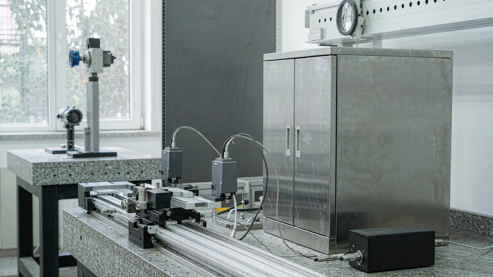
A single linear encoder readhead reports the position of its own sensing point. If the carriage yaws—even by an arcsecond—while translating, that rotation appears inside the position signal as a length error, and it reappears at the tool point scaled by the Abbe arm. Mounting a second readhead on the same scale, typically at the opposite end of the carriage or scale span, lets the controller separate the two motions: the average of the two signals is the pure translation, and half their difference is the rotation. Averaging the two positions removes the yaw contribution from the commanded position; the difference signal can drive explicit angular compensation at the tool point.
The technique is standard on long-travel granite stages, photolithography platforms and metrology machines where angular error, not scale accuracy, dominates the error budget. It is not free: the two readheads must be matched in configuration, their installation tolerances respected, and the controller must support dual-input processing. Used deliberately, dual readheads convert the largest systematic error in a long axis into a compensated quantity; used loosely, they add cost and diagnostics without changing what the workpiece sees.
ENGINEERING CONTEXT
Long precision stages fight a geometric problem, not a component problem. Carriage yaw of five arcseconds over a 300 mm Abbe arm is more than seven microns of tool-point error—larger than the scale's entire accuracy budget—and a single readhead is blind to it. The readhead sits on or near the yaw axis, so the rotation hides inside what it reports as position, and the machine discovers the error later as a squareness problem in the parts. The classical fixes—shortening the Abbe arm, stiffening the carriage, adding an autocollimator—are mechanical or metrological projects. The encoder-level fix is architectural: two readheads on one scale, averaged for translation and differenced for rotation. What keeps it from being routine is that it changes the feedback interface, the controller's signal processing and the installation procedure at once, and a dual-readhead axis integrated casually behaves no better than a single-readhead one.
Discuss your requirement ↗CRITICAL REQUIREMENTS
Both readheads must run the same pitch, interpolation, resolution and interface settings so their signals are comparable; mismatched settings turn averaging into corruption.
The motion controller must accept two position inputs, compute average and difference, and either feed the average to the position loop or expose both for compensation.
The two readheads should be installed at a known, maximized spacing along the yaw axis, aligned to the same scale datum, with mounting tolerances from the installation drawing respected.
Both position signals must be captured in the same control cycle; sampling skew between readheads injects velocity-dependent error into the difference signal.
BUYER MATRIX
Give every shortlisted supplier the same process definition and request configuration-specific proof.
| Aspect | Single readhead | Dual readhead, averaged | Dual readhead, average + difference |
|---|---|---|---|
| Position signal | Position of the sensing point, yaw included | Mean of two points: yaw removed from translation | Translation plus explicit rotation measurement |
| Abbe error at tool point | Full yaw × arm, uncompensated | Removed from the loop's position; residual from arm geometry remains | Actively corrected at the tool point in the controller |
| Rotation measurement | None—requires external autocollimator or level | Implicit: difference signal is proportional to yaw | Continuous inline angular signal for diagnostics and feedforward |
| Cost and integration | Baseline | Second readhead, cabling, configuration effort | Second readhead plus controller processing and commissioning |
A linear encoder measures displacement along the scale between the readhead and the scale's reference. The measurement is exact for the point where the readhead senses. When the carriage rotates by a small angle about a vertical axis somewhere on its body, every point on the carriage moves by a different amount along the direction of travel—and the readhead faithfully reports its own point's displacement, which includes a component from the rotation. The controller receives a position that mixes translation and rotation and cannot separate them, because one input cannot resolve two degrees of freedom.
The consequence scales with geometry. The rotation that contaminated the encoder signal also displaces the tool or workpiece point, and the displacement there equals the rotation multiplied by the distance between the rotation center and the tool point—the Abbe arm. A readhead near the rotation center reports almost no rotation-induced error, while the tool point tens or hundreds of millimeters away sees the full effect. This is why an axis can 'hold position' at the encoder while failing its accuracy specification at the workpiece: the feedback point and the error point are different points.
Two readheads at different positions along the yaw axis see different rotation-induced displacement components. Their signals now contain enough information to separate translation from rotation—one linear equation in one unknown becomes two equations in two unknowns. The same principle, applied to two readheads diametrically opposed on a rotary scale, cancels eccentricity; applied to readheads stacked to sense pitch, it extends to a second angular axis. The architecture generalizes wherever two sensing points sample a rigid body's motion.
With two readheads at positions separated by a known span along the yaw axis, each reports position plus a yaw-induced component proportional to its distance from the rotation center. The arithmetic is the point of the architecture: the average of the two positions equals the translation, because the rotation-induced components are equal and opposite about the center and cancel; the difference of the two positions, divided by the known span, equals the yaw angle itself.
Implementation details decide whether the arithmetic survives contact with hardware. The two readheads must be sampled in the same servo cycle, because a difference computed from unsynchronized samples measures velocity, not yaw. Their interpolation settings must be identical, because a resolution mismatch between channels biases the average. And the controller must either run the position loop on the averaged signal or run two loops with yaw feedforward—the choice follows the machine's dynamics and the platform's capability.
The difference signal has value beyond correction. Logged over travel, it is a continuous yaw map of the stage—a diagnostic that reveals guide wear, scale-liveling drift and bearing anomalies as trends in an axis that previously reported nothing about its own rotation. Machines that installed dual readheads purely for accuracy often find the angular telemetry becomes the more valuable output in service.
The cancellation quality is set at installation. The two readheads should be spaced as widely as the carriage and scale permit, because yaw measurement resolution from the difference signal is inversely proportional to the span—doubling the spacing halves the angle uncertainty for the same position noise. Both readheads must track the same scale with the specified air gap and lateral alignment, and the scale itself must be straight within its specification, since the readheads now measure against a common geometric reference rather than independent ones.
Matching matters as much as placement. Two readheads of the same model can still differ in phase, amplitude and interpolation offset if configured differently or mounted with different local geometry; the commissioning procedure should verify that with the stage stationary, the difference signal is stable and small, and that during a slow full-travel move the difference signal follows a smooth, repeatable curve. An abrupt step or sign flip in the difference signal at some position usually indicates a readhead tracking problem, a scale joint, or a local contamination event—not real yaw.
Cabling and diagnostics should follow the same discipline as any dual-channel feedback system: separate routing to the controller, alarms configured for signal-loss or mismatch on either channel, and a startup check that both channels report consistent position before motion is enabled. A dual-readhead axis that runs when one channel is dead is averaging garbage; the startup interlock is what makes the architecture trustworthy.
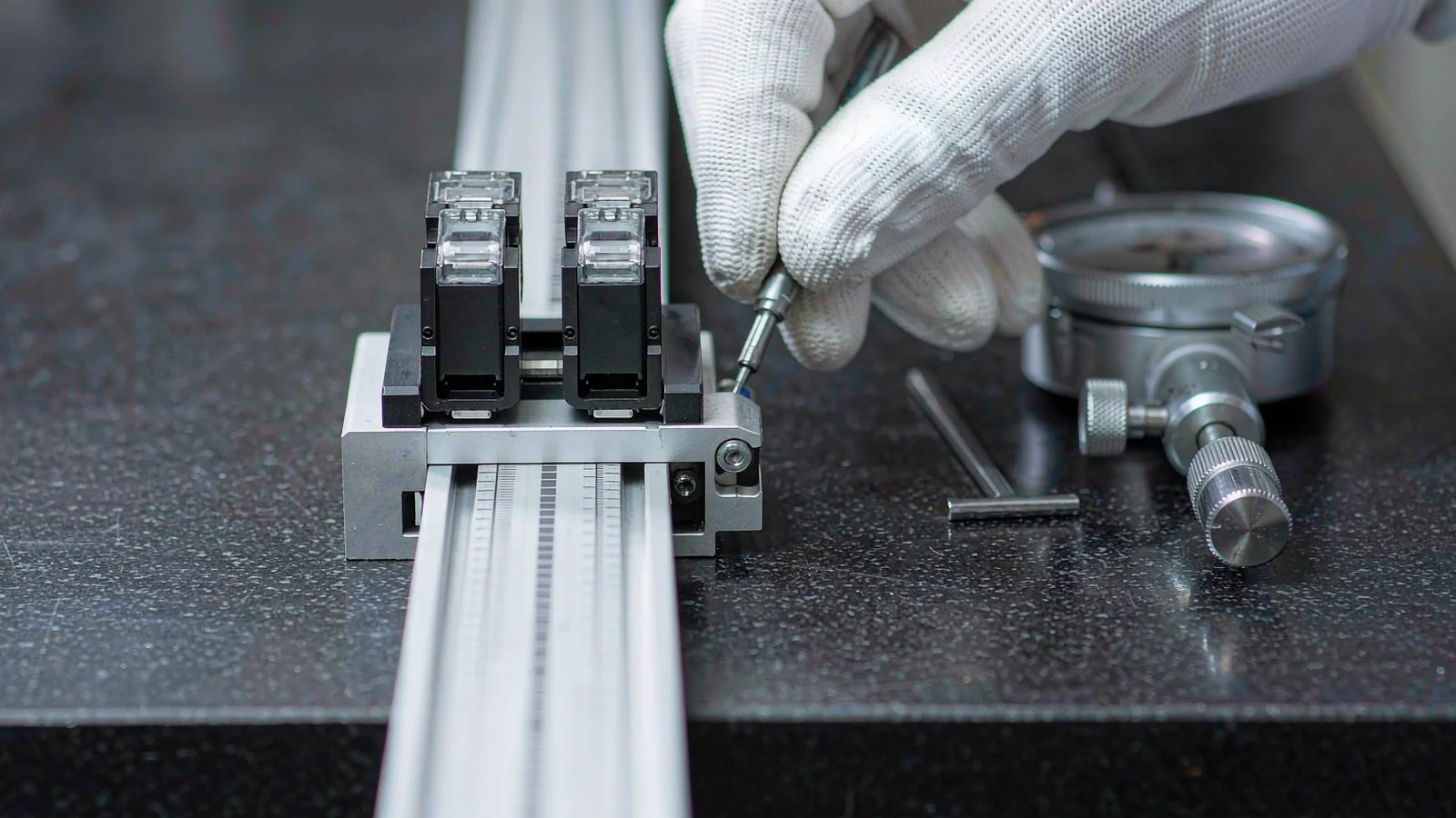
Dual readheads cancel angular error of the carriage relative to the scale. They do not make the scale more accurate; scale deviation still appears identically in both channels and passes through the average untouched. They do not correct straightness of the guides, squareness of the axis stack, or thermal expansion of the scale—those need their own budget lines. The technique addresses exactly one error source: the yaw (or pitch, or eccentricity) component that a single readhead hides inside its position report.
The payoff should therefore be evaluated against the error budget, not against a hope. On a long-travel granite metrology stage where yaw × Abbe arm is the dominant term after scale accuracy, dual readheads can remove the majority of the tool-point error and shrink the residual enough that simple error mapping closes the gap. On a short-travel compact stage with a stiff carriage and a millimeter-scale Abbe arm, the same hardware adds cost and failure modes while removing an error that was already negligible. The architecture is powerful where geometry makes it necessary—and geometry is the test.
Start by confirming the feedback architecture on paper: both readheads' configurations, the controller's dual-input mode, the sampling synchronization and the intended processing—average to the loop, difference to compensation or monitoring. Then commission in order: verify each channel independently against the scale datum, check the stationary difference signal, run a slow full-travel move and record the difference curve, and compare the derived yaw against an independent angular measurement—an autocollimator or electronic level—over several positions.
Only after the angular signal is validated should compensation be enabled, verified as every encoder compensation is: positioning measurements at the tool point, before and after, over full travel, in both directions. The before-and-after pair is the evidence that the cancellation works at the point that matters, and it becomes the baseline for the machine's future health checks.
CONCLUSION
A single encoder readhead answers one question—where is this point—while a precision stage asks two: where did it translate, and how did it rotate. Dual readheads on a common scale answer both, with the average feeding the position loop clean of yaw and the difference delivering a continuous angular measurement that doubles as a health diagnostic.
The technique pays where geometry makes angular error dominant: long travel, long Abbe arms, granite metrology platforms and lithography stages. Specified with matched configurations, spaced and aligned deliberately, synchronized by the controller and verified at the tool point, it converts the largest systematic term in a long axis's error budget into a measured, corrected quantity—rather than a surprise discovered in the parts.
EVIDENCE CHECKLIST
FAQ
As far apart as the carriage and scale geometry allow. The yaw angle derived from the position difference is divided by the readhead span, so a wider span gives better angular resolution from the same position signals. The exact positions and their tolerances should come from the installation drawing.
No. The averaged position signal has the resolution of the individual channels, not twice it, and noise does not halve simply because two channels exist. The benefit is the removal of the yaw contribution from the reported position and the availability of the rotation signal—not a resolution gain.
Yes. Two readheads mounted diametrically opposite on a rotary scale see eccentricity with opposite signs, so averaging cancels it—the same arithmetic as yaw cancellation on a linear scale. This is a well-established technique on large rotary tables where perfect scale centering is impractical.
The controller must accept two synchronized encoder inputs and either compute the averaged position for the servo loop or expose both signals plus the difference for compensation and monitoring. Sampling both channels in the same control cycle is essential; unsynchronized inputs turn the difference signal into a velocity measure.
Both architectures exist. Averaging into a single position loop is simpler and behaves like a conventional axis with a cleaner signal; dual-loop control with yaw feedforward can add active angular stiffness but is more complex to tune. The choice depends on the machine's dynamics and the controller platform's native support.
AUTHORITATIVE SOURCES
TECHNICAL REVIEW
Send the application, critical parameters and any drawing or process information available.
Discuss your application ↗