
Reference with sufficient sampling
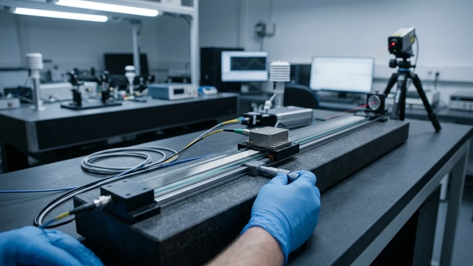
A laser interferometer or calibrated comparator sampled densely enough to resolve the signal period, not just the scale period.
TECHNOLOGY / OPTICAL ENCODER CALIBRATION
Encoder position error lives at two very different spatial wavelengths: scale grating pitch error that repeats every few millimeters and interpolation cycle error that repeats every signal period, often below a micron. This guide explains how to measure each contribution on its own terms and how to decide which compensation method fits which error.
Published
DIRECT ANSWER
Position error reported by an optical encoder is the sum of contributions at very different spatial wavelengths. Scale pitch error originates in the grating itself: the ruled lines deviate from their nominal spacing, so the error repeats every scale period—tens of microns to a few millimeters—and builds slowly along the travel. Cycle error, sometimes called interpolation error, originates in the readhead optics and signal electronics: imperfect quadrature, gain mismatch and harmonic distortion in the sine and cosine signals repeat every signal period, which after interpolation can be a fraction of a micron.
The two errors are separated by their spatial signatures, not by a single measurement. A high-density scan over a short travel reveals the cycle error riding on the pitch error; a lower-density scan over full travel reveals the accumulated pitch pattern. Once separated, each maps to a different fix—pitch error to a travel-dependent error map or a better scale, cycle error to signal tuning or interpolation calibration—and applying the wrong method to the wrong error wastes effort while the error remains.
ENGINEERING CONTEXT
An encoder datasheet reports a combined accuracy grade and a subdivision error figure, but the machine shows position error that matches neither number. Inspection with a reference instrument returns a periodic-looking trace, with structure hiding at wavelengths shorter than the measurement sampling. Teams then compensate with a linear error map built from sparse points, which removes the long-wavelength travel terms while leaving a repetitive short-range error that appears as velocity ripple and jitter in the application. Without separating pitch error from cycle error, calibration effort goes to the term that is easiest to measure rather than the one that dominates.
Discuss your requirement ↗CRITICAL REQUIREMENTS
A laser interferometer or calibrated comparator sampled densely enough to resolve the signal period, not just the scale period.
Full-travel scans at moderate density for pitch behavior; short-travel high-density scans at several positions for cycle behavior.
Lissajous figures, quadrature phase and amplitude data collected alongside position measurements to attribute cycle error to its source.
Error traces analyzed by spatial wavelength so each spectral component is assigned a cause and a compensation method.
BUYER MATRIX
Give every shortlisted supplier the same process definition and request configuration-specific proof.
| Error family | Spatial wavelength | Dominant causes | Fitting responses |
|---|---|---|---|
| Scale pitch error | One scale period (tens of microns to millimeters), plus long-wavelength travel terms | Grating ruling deviations, substrate distortion, scale mounting stress | Travel error map, scale replacement or remounting |
| Cycle error | One signal period after interpolation (sub-micron) | Quadrature phase error, gain mismatch, harmonic distortion, electronics offset | Signal tuning, gain and offset adjustment, interpolation calibration |
| Long-wavelength error | Meters to full travel | Scale installation alignment, thermal expansion, scale material mismatch | Linear error map, thermal control, scale material selection |
| Reversal error | Direction-dependent at any wavelength | Hysteresis, readhead gap changes, mechanical loveness | Bearing and mounting correction, bidirectional mapping |
| Random error | No fixed wavelength | Contamination, electrical noise, vibration at measurement time | Environment and electrical hygiene, not compensation |
Compensation stores corrections against position, which assumes the error is a stable function of position. Scale pitch error satisfies that assumption: the grating is fixed to the machine, so its deviations repeat at the same physical locations for the life of the installation. Cycle error also repeats, but at such a short wavelength that an error map sampled at practical intervals cannot represent it—points a millimeter apart alias the cycle error into noise, and the map averages it away while the motion system keeps feeling it as velocity ripple.
This is the practical reason for separation: the two errors need different data density and different correction mechanisms. A map that tries to serve both ends up serving neither, and the symptoms—surface finish marks at the scale period, tracking error that grows with speed—persist after compensation that looked correct on paper.
Cycle error measurement needs a reference sampled well beyond the scale period—ideally tens of points per signal period, which for a fine scale means interferometer readings on millimeter-long strokes at very fine steps, or a calibrated short-range comparator. The scan is repeated at several positions along the scale, because cycle error amplitude varies with signal quality: readhead alignment, contamination and scale coupling all modulate it.
The signature is unmistakable once resolved: an error that completes exactly one cycle per signal period, typically from tens of nanometers to a fraction of a micron. Correlate it against the signal domain—plot position error versus the sine-cosine Lissajous phase at the same instants and the attribution becomes direct. First-harmonic error tracks gain mismatch and quadrature error; second-harmonic tracks signal distortion. This correlation turns a mysterious position ripple into a named, tunable defect.
Pitch error asks a different question: how faithfully does the grating convert real displacement into counts over the full travel, and with what periodic structure? The measurement is a full-travel scan with sampling fine enough to see the scale-period term—typically four to eight points per scale period—under stable thermal conditions so drift does not masquerade as pitch behavior.
Analysis then works in the spatial domain. A Fourier or periodogram view of the error trace shows three regions of interest: the long-wavelength terms from installation alignment and thermal state, a peak or cluster at the scale period that is the pitch error, and any elevated floor at the signal period reflecting cycle error leaking into the scan. Each region maps to its own response: long-wavelength terms to a low-order error map, a genuine pitch peak to the scale vendor or a periodic compensation entry, the signal-period floor back to the cycle-error workflow above.
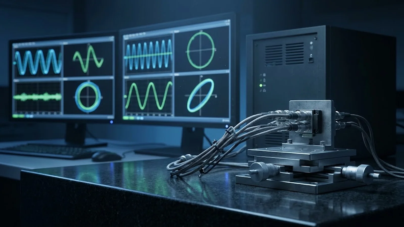
With the errors separated, compensation decisions become mechanical. Cycle error responds best at its source: readhead gain and offset adjustment, quadrature phase trimming, or interpolation calibration performed by the drive. Where the signal cannot be improved, some controllers accept a cycle-period compensation table, but entry counts multiply quickly at fine scales and the correction only holds while signal quality holds—a fallback, not a first choice.
Pitch error responds to periodic compensation keyed to the scale period or to the scale itself. Before compensating, check the mounting: fastening stress and readhead gap variations produce pitch-like signatures that disappear when the installation is corrected. And keep the order—tune the signal path first, then capture the error map, because a map captured on an untuned signal bakes cycle error into its points.
The workflow below fits a normal calibration visit and produces a defensible split of the encoder error budget. Repeated on every serviced machine, it shows which error family dominates each encoder model in each environment—and treats the results as living data, since signal quality drifts with LED aging and pitch behavior shifts when scales are remounted after maintenance.
CONCLUSION
Encoder position error is not one number but a spectrum of spatial wavelengths, and the two most consequential—pitch error at the scale period and cycle error at the signal period—demand different measurements and corrections. Dense short-stroke scans expose the cycle error and trace it to signal defects; full-travel scans with spatial-frequency analysis expose the pitch structure and separate it from installation and thermal terms.
The discipline pays for itself in compensation that works: signal corrections applied where they belong, error maps captured after the signal is clean, and periodic re-separation as hardware ages. When each error carries its own name and wavelength, encoder accuracy becomes a managed property instead of a datasheet promise.
EVIDENCE CHECKLIST
FAQ
Scale pitch error repeats once per scale period—tens of microns to millimeters—and comes from the grating itself. Cycle error repeats once per signal period, often well below a micron after interpolation, and comes from readhead optics and signal electronics: quadrature error, gain mismatch and distortion.
Generally no. Map sampling at practical intervals is far coarser than the signal period, so cycle error aliases into the measurement and the map cannot represent it. Cycle error is corrected at the signal source through tuning or interpolation calibration.
Aim for tens of reference points per signal period over strokes shorter than a few scale periods, repeated at several positions. This resolves the cycle amplitude and shows whether it is stable along the scale.
Cycle error is the usual suspect: as the stage crosses each signal period, the repeating error forces the velocity loop to correct continuously. A ripple synchronized to the scale period points to pitch error.
Before. A map captured on an untuned signal freezes aliasing artifacts into the compensation points. Verify signal health, tune quadrature and gains, then capture the map for the residual error.
AUTHORITATIVE SOURCES
TECHNICAL REVIEW
Send the application, critical parameters and any drawing or process information available.
Discuss your application ↗