
A specified hysteresis value
The supplier's bidirectional error figure for the exact encoder configuration, with the measurement method and direction of the stated tolerance.
TECHNOLOGY / ENCODER ACCURACY
Why a precision axis measures one position approaching from the left and a different one approaching from the right. This guide explains encoder-side hysteresis, separates it from machine reversal error, shows how to measure it and defines what the specification does and does not promise.
Published
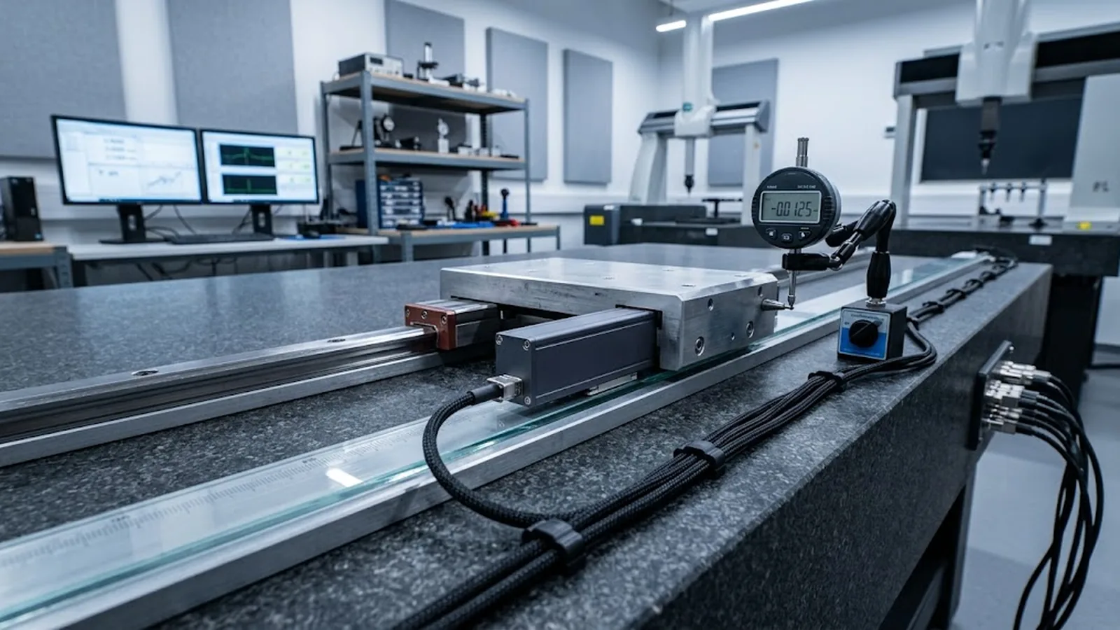
DIRECT ANSWER
Bidirectional error, commonly called hysteresis, is the position difference reported when the same physical point is reached from opposite directions of travel. In an optical encoder it is not mechanical backlash in the classic sense: the readhead does not touch the scale. It arises from elastic and inertial deflection of the scale or its mounting under friction and acceleration forces, from play between readhead and its bracket, and in coupled rotary systems from the shaft and coupling. Typical specified values range from a few nanometres on well-clamped glass scales to tens of micrometres on loosely coupled or steel-tape systems.
Measure it by approaching a target from both directions repeatedly and comparing the reported positions, using a reversal method with an independent reference such as a laser interferometer or a reversal artefact for machine-level results. To separate encoder hysteresis from machine reversal error, measure the encoder signal itself with the readhead stationary while the scale is displaced and released, or compare axis results with the readhead uncoupled from the mechanics. Encoder hysteresis is a component property stated in the datasheet; total bidirectional error of the axis is a system property that the machine builder owns.
ENGINEERING CONTEXT
A stage repeats to a few nanometres unidirectionally, yet parts measured from one side and machined from the other do not agree, and a bidirectional round-robin test shows a closed loop that fails to close. Buyers frequently attribute this to ballscrew backlash and order mechanical service, only to find the problem persists on a direct-drive stage with no gearbox at all. The overlooked contributor is hysteresis in the position feedback itself: the scale flexes on its mounting, the readhead bracket has micro-play, or the coupling between motor shaft and encoder winds up under reversing torque. The specification sheet states repeatability and accuracy but the hysteresis line is missing, misunderstood as backlash, or quoted under conditions that do not resemble the installed axis.
Discuss your requirement ↗CRITICAL REQUIREMENTS
The supplier's bidirectional error figure for the exact encoder configuration, with the measurement method and direction of the stated tolerance.
A test plan that distinguishes encoder-side hysteresis from ballscrew backlash, bearing play and guide friction, so corrective effort targets the real contributor.
Scale tape or glass mounted per the supplier's adhesive and clamping specification, readhead brackets machined rigid, with thermal expansion provisions that do not introduce play.
Where hysteresis cannot be eliminated, defined approach direction, pre-travel overshoot or bidirectional compensation tables agreed with the control supplier.
BUYER MATRIX
Give every shortlisted supplier the same process definition and request configuration-specific proof.
| Contributor | Physical mechanism | Typical magnitude | How to isolate it |
|---|---|---|---|
| Scale mounting compliance | Scale or tape flexes on adhesive or clamps under friction and acceleration, then recovers | Tens of nm to a few µm | Displace and release the scale with the readhead fixed; watch the signal return path |
| Readhead bracket play | Micro-clearance or elastic wind-up between readhead and carriage | Sub-µm to a few µm | Indicator on readhead body while jogging the axis in both directions |
| Shaft and coupling wind-up (rotary) | Torsional elasticity under reversing torque | Arcseconds to arcminutes at the shaft | Dual-encoder test: one at motor, one at load |
| Machine reversal error | Ballscrew backlash, bearing play, guide stiction | µm to tens of µm | Laser interferometer reversal test with the encoder signal logged in parallel |
| Interpolation asymmetry | Signal imbalance shifts the interpolated zero differently by direction | Sub-µm, often negligible | Lissajous signal check; compare with subdivision error test data |
In a gear or a ballscrew, backlash is lost motion: clearance that the mechanics must traverse before force is transmitted. An optical encoder has no such clearance between scanning head and scale, so its hysteresis has a different origin. The dominant mechanism is elastic: when the axis reverses, friction and inertia loads momentarily deflect the scale relative to the readhead, or the readhead relative to the carriage. Glass scales clamped only at their ends bow slightly; steel tape scales on adhesive lift marginally at the scanning zone; a readhead bracket with clearance allows the head itself to shift a few micrometres under the reversing load and return afterward.
The result is that the position signal lags the true reversal and recovers as loads settle. The encoder reports the position faithfully as it sees it, but what it sees depends on the direction of approach. This is why hysteresis cannot be calibrated away in the same way as a repeatable scale error: the offset is load- and history-dependent, so compensation works only approximately and only for stable, repeatable contributions.
The axis-level symptom—different positions reported from opposite directions—is the sum of every contributor in the loop. Before ordering corrective work, isolate the feedback. The fastest component-level test requires no disassembly: command the axis to a mid-travel target, approach it unidirectionally from one side many times, then from the other, and log the raw encoder counts with the servo holding position. Mechanical loads settle within milliseconds; a signal that continues drifting toward the unidirectional mean over seconds indicates scale or bracket compliance recovering elastically.
For a definitive separation, run the reversal test twice: once with the normal mechanical loop, once with the motor decoupled so the scale can be translated by hand between two fixed readheads or against an external interferometer. The difference that remains when mechanics are removed from the loop is the encoder's own hysteresis. Machine builders who skip this step routinely spend days correcting a ballscrew that was never the problem.
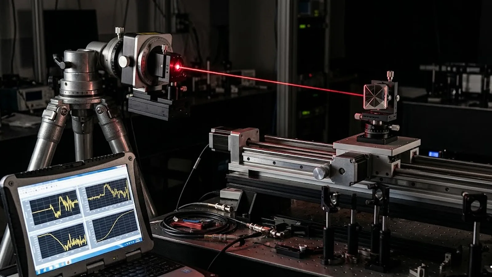
A meaningful measurement states four things: the target positions, the approach pattern, the settling time before the reading, and the temperature. The standard pattern is a bidirectional round-robin—approach each target from both sides, several cycles—plotted as a position-versus-direction hysteresis loop. The loop's width at each target is the local bidirectional error; the loop's shape reveals whether the cause is a simple constant offset or a position-dependent compliance, which points at scale mounting rather than bracket play.
Two practical traps distort results. First, reading too early: the elastic recovery after a reversal takes time, so a settled reading must be defined—typically holding position for hundreds of milliseconds before sampling. Second, attributing interpolation asymmetry to hysteresis: a signal imbalance that shifts the interpolated zero in a direction-dependent way looks identical at the position output. A Lissajous check of the quadrature signals distinguishes the two, and suppliers can supply subdivision error data for the configuration.
Most encoder hysteresis is a mounting problem, not a sensor problem. Glass scales should be clamped or bonded per the supplier's pattern so that thermal expansion is accommodated without allowing the scanning zone to move under friction loads. Tape scales need the specified adhesive system over the full length, with correct curing pressure, because a partially bonded tape acts as a leaf spring. Readhead brackets deserve the same rigor as the scale: machined faces rather than shims, fastener patterns that clamp rather than locate, and no cable routing that can pull the head against its clearance.
Where the loop cannot be stiffened further, the machine can still be made bidirectionally accurate. Three strategies cover most processes: always approach critical positions from the same direction with a defined overshoot, which converts bidirectional error into unidirectional repeatability; use bidirectional error maps in the control, effective when the hysteresis contribution is stable and the mechanical reversal error has already been compensated; and specify the encoder configuration with the lowest documented hysteresis where the process genuinely requires it, accepting that this is a component selection decision rather than a tuning exercise.
Ask for hysteresis as a configuration-specific number: the value for the ordered scale type, mounting method and readhead, together with the measurement method used to derive it. A family-level typical figure measured on a laboratory fixture tells you little about a tape scale bonded to an aluminium carrier at the far end of the machine. For rotary feedback, ask for the torque-dependent angle error of the shaft-coupling arrangement as installed.
On the build side, require the scale bonding and clamping records and a bracket inspection at incoming stage, and commission with a bidirectional round-robin whose result is archived as the axis baseline. When the axis is later re-verified, comparing loop width against the baseline detects developing compliance—adhesive creep, loose clamps—long before it becomes a dimensional problem on parts. Hysteresis handled this way stays a specified, bounded property instead of an intermittent customer complaint.
CONCLUSION
Bidirectional error in an optical encoder comes from elastic and inertial deflection in the scale mounting, readhead bracket and couplings—not from contact backlash. It is measurable with a disciplined bidirectional round-robin and separable from machine reversal error with a component-level test.
Specify the hysteresis figure for the exact configuration, build the feedback path stiffly enough that the figure survives installation, and give the process a direction strategy where residual error remains. An axis managed this way measures the same point from both sides within a bound you can defend.
EVIDENCE CHECKLIST
FAQ
No. Backlash is lost motion from mechanical clearance in the drive train. Encoder hysteresis is the direction-dependent offset of the position signal caused by elastic and inertial deflection of the scale, its mounting and the readhead bracket. A direct-drive stage with no backlash can still show encoder hysteresis.
It depends on the configuration. Well-clamped glass scales with rigid readhead brackets are specified in the range of a few tens of nanometres to a few hundred; adhesive-bonded tape scales and loosely mounted readheads can reach single-digit micrometres. Only the configuration-specific datasheet figure is a usable number.
Only the stable, repeatable part of it. Bidirectional error maps work when the hysteresis contribution is consistent and the mechanical reversal error has been addressed first. Load-dependent elastic recovery is only approximately repeatable, so approach-direction control remains the more robust strategy for demanding processes.
Log raw encoder counts while holding position at a target approached from both directions: continued drift toward the unidirectional mean over seconds indicates scale or bracket compliance. For definitive separation, repeat the reversal test with the mechanics out of the loop—scale translated against a fixed readhead or an external interferometer.
Most repeatability figures are unidirectional and therefore exclude hysteresis. If your process approaches critical positions from both directions, the relevant property is bidirectional repeatability or reversal error of the complete axis, which is always larger than the unidirectional figure. Ask which definition the quoted number uses.
The scale type and length, mounting method, readhead model, axis loads and acceleration, and any reversal test data you already have. SENFU can review the mounting design, quote the configuration-specific hysteresis figure and recommend a measurement plan for the assembled axis.
AUTHORITATIVE SOURCES
TECHNICAL REVIEW
Send the application, critical parameters and any drawing or process information available.
Discuss your application ↗